Integrating-averaging Sound Level Meter Type 2240 – Instruction Manual12
3.6 EMC Test Procedures
3.6.1 Signal Source for Immunity Test
The acoustic signal, which is used during the Immunity test, is applied to the microphone through a
½ ″ plastic hose (a normal water hose) from a source outside the test room. In this way, the acoustic
source is not affected by the RF field. The source can be a normal entertainment earphone.
Fig.3.1
Connecting the
microphone to the
signal source for
immunity testing
To prevent the acoustic source from being affected by acoustic noise in the surroundings, the following
method can be used:
Insert an acoustic attenuator in the hose close to the microphone, so that the sound pressure within the
greater part of the hose is held far above the surrounding sound level. The acoustic attenuator can
easily be made from a short piece of metal tubing with an outer diameter of ½ ″. Squeeze a piece of
paper tissue into the tube, and compress it until the desired attenuation is obtained. Up to 40 – 60 dB of
acoustic attenuation can be obtained.
3.6.2 Reference Orientation
Fig.3.2
Reference
orientation relative
to RF emitter/
receiver
3.6.3 Testing EMC According to IEC 60804
The exponential, time-averaged detectors in Sound Level Meter Type 2240 are digital and their results
calculated based on the same samples used for calculating the linear averaged detectors.
Therefore, the LxFInst measurement values will be equal to short Lxeq values when measuring steady
signal levels.
For this reason, measurements of LxFInst must be used during testing for Immunity to RF signals
when testing according to both IEC 60651 and IEC 60804. That is, only one test has to be carried out
and no special operating mode, giving a short-duration Lxeq measurement, is provided.
Microphone assembly
(wind screen removed)
Water hose
50dB SPL inside
Acoustic
attenuator
Compacted
paper tissue
Water hose to
acoustic source
>90dB SPL inside
040132
040253
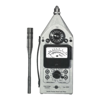
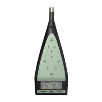
Type 2240

 Loading...