2.1. FRONT PANEL
Type
2512
Human-Respon••
Vibration Meter
2.1.1. Power and Input Controls
POWER:
28 V 2 mA:
2.
CONTROLS
O,l
-0.63
Hz
Motion S,ckness
•
Z-•;:uced
Comfort
Severe
.
·-""'
•
Brilel&J(ja,r
Vilmition
level
RMS
!11
A Add
20
dB)
Power
28 V
2mA
,()-i
,------Input-------,
1
(X)
2(Y)
3
(Z)
1 2 3
Ref
, I
Seat-
0
9
~
Accel-
'_r:
·_
......
.
...
_
ero7eter
xvz___;
·
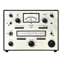
Fig.
2.1.
Power and signal input controls
"Off"
-
In
this position the instrument is switched off and the contents of the
memory are erased. However, if rechargeable Nickel Cadmium cells are
being used, they can still be recharged when the switch is in this position.
"On" - Power is on in this position and the battery voltage indicator should
move from the red to the blue region, indicating that the voltage from the
batteries, or from the external power supply where used, is sufficient for
proper, reliable operation.
In
addition a number
of
the indicating light
emitting diodes will come on, corresponding to the switch positions select-.
ed during the previous measurement, and the two displays will begin to
indicate. Warm-up time depends on the mode of operation, 5 s for HAND-
ARM,
10 s for WHOLE BODY 1 - 80
Hz,
and 40 s for 0, 1 - 0,63
Hz
MOTION
SICKNESS. The
2512 can be powered either from internal batteries
or
from
external supplies. See section
3.2.
28 V
(2
mA) micro-socket for supplying power to, for example, high sensi-
tivity accelerometer Type
8306.
9

 Loading...