Although it is not recommended, the Seat-Transducer Type 4322 can be dismantled so that the
transducer element can be removed and mounted on the vibration table of the Accelerometer
Calibrator if required.
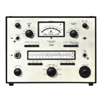
The Accelerometer Calibrator Type 4291, shown in Fig.3.9., provides a test vibration
of
10
ms-
2
peak
(1
g for early models) at a frequency of 79,5
Hz.
This lies within the frequency
range
of
the Hand-Arm and Whole Body measurement ranges, but outside the Motion
Sickness range, and cannot therefore be used to check this function.
Fig. 3.9. The Type 4291
Accelerometer
Calibrator
The procedure is as follows:
1.
Determine the mass
of
the accelerometer from the calibration chart supplied with it.
2.
. Mount the acclerometer finger tight to the vibration table of the Calibrator via a 10-32
UNF
stud. The 3 mm to 10-32
UNF
adaptor
(DB
1425)
should be used with accelerometers with
a 3 mm stud. Accelerometers without either a stud or a tapped hole for a stud should be
fitted to the cementing stud
(DB
0756) with wax or cement.
3.
If using the internal battery supply of the
4291,
switch the FUNCTION SELECTOR to "Batt.
Check". If the meter deflection is below the "BATT." region on the scale, the batteries
should be replaced.
4.
Switch the FUNCTION SELECTOR to "Internal Gen." The Calibrator will now vibrate the
accelerometer at 79,6
Hz
(500
radians.sec-
1
).
5.
Adjust the ACC. LEVEL control of the
4291
until the meter pointer coincides with the load
mass on the
"grams
O
...
100" scale. The load mass is the total mass attached to the
vibration table, usually the acce!erometer to be calibrated and the stud (usually negligible).
The accelerometer is now subjected to
an
acceleration of
10,0
ms-
2
peak ±
2%.
6.
"Preset" the Type 2512 by pressing both of the MEASUREMENT pushkeys simultaneous-
ly. The LEDs in both keys will come on to indicate that the registers have been cleared and
that the instrument has been initialized and ready to begin a new measurement. Only
in
this state can the measurement mode be selected.
25

 Loading...