Note:
The above step 8 in the procedure does
not
synchronize the time
of
start
of
the measurement
as initiated from the 2512 with the time
of
the first printout as defined
by
the printer's internal
clock, although the time interval between subsequent printouts will be as set on the printer's
CLOCK
CONTROL SELECTOR. The first printout will occur when the printer's internal clock
first reaches a value which is a whole number
of
these preset intervals. For example,
if
the
CLOCK
CONTROL SELECTOR is set
to
"1
min"
on the 2312, the first printout will occur when
the clock reaches a whole minute, regardless
of
how
long has elapsed since the measurement
was started from the 2512, and printouts will occur at minute intervals thereafter. If, however,
the CLOCK CONTROL SELECTOR is set
to
"10
s",
the first printout will occur when the clock
reaches a time which is a round number
of
10
s,
i.e.
00,
10,
20,
30,
40, 50
s,
and printouts will
occur
at
10
s intervals thereafter.
It is possible
to
synchronize the measurement start time and the printout time by continually
checking the printer's internal time
by
pressing the left
of
the
two
PRINT switches down
to
the
"Time"
position, and starting the measurement by pressing
"Start"
on the 2512 immediately
the minute value changes. The PRINT switch on the 2312 should be returned to the
"Time
&
Data"
position simultaneously. The printer will
now
print out the data
for
the start time and
subsequent printouts will
occur
at the interval selected on the CLOCK CONTROL SELECTOR
of
the 2312.
If the actual time
of
day is not
of
importance, the internal clock
of
the printer can be reset
to
00:00:00 and the measurement started
from
the 2512
at
the same time as follows:
1.
Turn the CLOCK CONTROL SELECTOR on the front panel
of
the printer
to
any
of
the four
"Preset
Clock"
positions.
2.
Start the measurement
from
the 2512 by pressing the MEASUREMENT
"Start"
pushkey
and reset the time on the printer by raising the CLOCK paddle switch
to
the
"Reset"
position and turning the printer's
CLOCK
CONTROL SELECTOR
to
the required
"Print
Interval" immediately afterwards.
The data list will
now
be printed
at
the start time and at the selected
"Print
Interval"
subsequently.
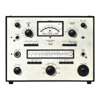
4.2. USE WITH THE PORTABLE LEVEL RECORDER TYPE 2306
The Portable Level Recorder Type 2306 shown in Fig.4.2. (or the
two
channel Type 2309) may
be used to obtain an accurate hard
copy
of
vibration levels recorded
by
the 2512 in the field. A
vibration level can be recorded
from
the 2512 onto the Portable Level Recorder Type 2306
from
either the
DC
OUTPUT (which takes the DC signal just after it has passed through the Log
RMS detector
of
the Type 2512)
or
the OUTPUT TO EXT. FILTER (which takes the
AC
signal
just before
it
passes through the Log RMS detector) on the rear panel
of
the Type 2512.
With DC recording, the 2512 is used
to
rectify and average the signal before
it
is fed
to
the re-
corder. The time constant is therefore accurately determined by the Type 2512.
In
the
"Preset"
mode, the time constant is very much shorter
(0,
125
sin
the HAND - ARM and WHOLE BODY 1
- 80
Hz
modes, and 0,6 s in the WHOLE BODY
0,
1 - 0,63
Hz
MOTION SICKNESS mode)
to
give
a very short settling time when changing measurement mode. DC recordings may be made
with this
mode
active, in which case the time constant
of
the signal recorded is as stated
above, although
of
course measurements cannot be carried out on the 2512 at the same time.
It is recommended that level recordings are made using the
"DC
Lin." RECORDING MODE
of
the level recorder and the DC OUTPUT signal
of
the 2512 in preference to the
AC
signal,
whenever possible.
31

 Loading...