therefore be converted to a charge input to the 2512. This is most conveniently accomplished
using one
of
the adaptors available for this purpose, e.g.
WB
0251, for direct conversion, or
WB 0706 with
20
dB attenuation, or the Attenuator Set WB 0473, which provides attenuations
from
40
dB to -10 dB in
10
dB steps. These adapters may also be used together with the
Measuring Amplifier Type 2610 or Electronic Voltmeter Type 2425 to allow tape-recorded
signals to be matched in level to the fixed range
of
the
2512.
The various possibilities are
shown in Fig.10.
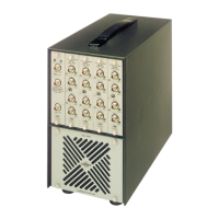
4.4.1. Recording Data for Later Analysis by the 2512
38
The system of Fig.4.9. is recommended. The Triaxial Accelerometer Type
4321
is suitable for
measurements on both hand tools and vibrating objects which support the standing or sitting
person. The Seat Transducer Type 4322 is specially designed for measuring the vibration
applied directly. via the buttocks to a sitting person, and is strongly recommended for this
purpose. The instruments in the measurement arrangement should be connected as shown in
Fig.4.9. The recommended recording procedure is as follows:
1.
For each axis of the accelerometer, set up its Charge Amplifier Type 2635 as described in
its Instruction Manual.
In
particular, ensure that the correct transducer sensitivity (given
for each axis individually on the
4321
calibration chart) is dialled in for each axis
of
the ac-
celerometer (or Seat-Accelerometer Type 4322, if used), and that the instrument is set up
to output in
ms-
2
with a lower limiting frequency of
0,2
Hz.
This covers the entire HAND -
ARM region and the WHOLE BODY region down to within
0,
1
Hz
of the its lower limiting
frequency. It is recommended that the Upper frequency limit is set at
0.1
kHz for WHOLE
BODY measurements and
1 kHz for HAND - ARM measurements.
2.
On
the Tape Recorder Type
7005,
set the following major controls:
ERASE
TAPE SPEED
FLUTTER COMPENSATION
"Off"
"38.1
mm/s"
"Off"
3.
For each channel to be used on the Tape Recorder Type
7005,
set the following controls
on the respective channel module:
MODE SWITCH
INPUT ATTENUATOR
"DC"
"30dB"
The
"DC"
position allows recording
of
signals right down to DC and in combination with a tape
speed of
38.1
mm/s
gives a frequency range
of
DC to
1.25
kHz, which conveniently spans the
range of human vibration measurements, i.e. from
1
Hz
to
80
Hz
for Whole Body measure-
ments and from 8
Hz
to 1 kHz for Hand - Arm measurements.
The INPUT ATTENUATOR position "30
dB"
gives full scale deflection on the monitor meter of
the tape recorder for a
1 V signal on the input. For further information on the use of the tape
recorder, please refer to its Instruction Manual.
4.
With the signal to be recorded connected, adjust the mV / UNIT OUT switch on the 2635 or .
the INPUT ATTENUATOR on the tape recorder to give full scale deflection on the meter of
the tape recorder without lighting the overload warning lights.either on the 2635
or
on the
tape recorder. Care must be taken at this stage to ensure that the peak values
of
signals
with a high crest factor lie within the range
of
measurement without causing overload. The
degree
of
amplification (or attenuation if high signal levels are involved) must be noted for
use later during the analysis process to match the output signal from the tape recorder to
the input levels assumed by the
2512,
i.e. a charge input of 1 pC corresponding to
an
acceleration of 1
ms-
2
.

 Loading...