Using a Number of 2512s in a Measurement Arrangement
More then one
2512
may be used
in
a measurement system as shown
in
Fig.5.2.
In
this case
the state
of
the INTERFACE pushkeys on the 2512s determines whose data is transmitted to
the recording devices. Only one
2512
at a time can transfer data, the one whose INTERFACE is
active. The INTERFACE
"On/
Off"
switch is thus used to select the required
2512.
The
procedure is exactly the same as in section
5.3.2.
1
·c:io
I • , . 0 -
........
000
-
Alphanumeric Printer
Type 2312
1·
c:io
I I
'.
!"
• - .
oo
o -
Digital Cassette
Recorder
Type
7400
Human-Response
Vibration
Meters
Type2512
• .
CJD
I • , . 0 -
......
.,
000
-
810434
Fig.
5.2.
Connecting a number
of
25.12s
to external devices using the
/EC
Interface Bus
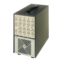
It should be noted, however, that no two 2512s can have
an
active INTERFACE at the same
time. One should always be switched off before the next is activated. If this is not done, neither
has priority over the
other and there is a danger
of
the two instruments trying to send data to
each other, leading to
an
unstable situation
in
which the recording device records invalid data.
5.3.3: Addressable Mode: Using an External Controller to Address the 2512 Individually
46
Hu man-Response
Vibration
Meter
Type2512
Alphanumeric
Printer
Type
2312
Desk
Top
Calculator
810435
Fig.
5.3.
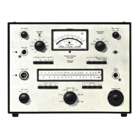
Using the 2512 as an addressable device in a system with a
desk-top calculator acting as an external controller
When a
2512
or
a number
of
2512s is used in
an
instrumentation arrangement with
an
external
controller such
as
a desk-top calculator
or
mini-computer, see Fig.5.3., each instrument
connected to the interface bus is addressed by a unique address which is set on the ADDRESS
SWITCH on the rear panel
of
the instrument, ·see Fig.5.4. The address is set in ASCII 7-bit
code, where bit 7 and bit 6 are always assumed to be
"1"
and "O" respectively. All codes
except
11111
are permitted.
11111
corresponds to unlisten, and should never be set.

 Loading...