Chapter 5 — Free-field
1
/
2
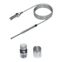
" Microphone Type 4191
Capacitance
Falcon™ Range of Microphone Products
Microphone Handbook
BE1377– 12
5
−
19
5.7 Capacitance
The microphone’s impedance is determined by its polarized capacitance. In addition,
the preamplifier’s input resistance and capacitance load the microphone. This load-
ing determines the electrical lower limiting frequency and the capacitive input at-
tenuation. However, with modern preamplifiers, this loading is very small and is
included in the preamplifier gain, G (see section 5.2.2). Only in special cases with
high capacitive loading does the fall in capacitance with frequency have to be taken
into account.
Typical capacitance (at 250 Hz):
18pF.
The capacitance is individually calibrated and stated on the calibration chart.
5.8 Polarization Voltage
Generally, a microphone is operated at its nominal polarization voltage. For Free-
field
1
/
2
" Microphone Type 4191, this is 200V. As this polarization voltage is posi-
tive, the output voltage is negative for a positive pressure applied to the dia-
phragm.
In special cases where there is a risk of preamplifer overload or there are long
cables to be driven, choose a lower voltage. This will cause a lower sensitivity (see
Fig.5.20) and a change in the frequency response (see Fig.5.21).
Fig.5.19 Variation of capacitance with polarization voltage and frequency
940604e
250 V
200 V
150 V
28 V
100 1k 10k 100kHz
10
12
14
Capacitance (pF)
16
18
20
Frequency (Hz)
 Loading...