Chapter 8 —
1
/
2
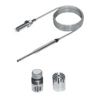
" Microphone Preamplifier Type 2669
Specifications Overview
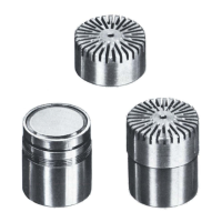
Falcon™ Range of Microphone Products
Microphone Handbook
BE1380– 12
8
−
11
8.9 Specifications Overview
8.10 Ordering Information
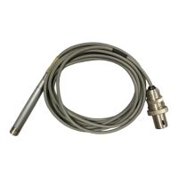
Extension Cables
LEMO — LEMO:
AO0414
Extension Cable 3m (9.8ft.)
AO0415
Extension Cable 10m (32.8ft.)
AO0416
Extension Cable 30m (98.4ft.)
EL4004/xx
Extension Cable length xxm (specified by customer)
Brüel&Kjær — Brüel&Kjær:
AO0027
Extension Cable 3m (9.8ft.)
AO0028
Extension Cable 10m (32.8ft.)
AO0029
Extension Cable 30m (98.4ft.)
FREQUENCY RESPONSE (re. 1 kHz):
3 Hz to 200 kHz,
±
0.5dB
ATTENUATION:
0.25 dB (typical)
PHASE LINEARITY:
≤±
3°
at 20Hz to 100 kHz
PHASE MATCHING:
0.
3°
at 50 Hz
INPUT IMPEDANCE:
15 G
Ω
||
0.45 pF
OUTPUT IMPEDANCE:
25
Ω
MAX. OUTPUT CURRENT:
20 mA (peak)
Note
: The max. output current can be limited by
the power supply.
MAX. OUTPUT VOLTAGE:
Total supply voltage –10V (V
peak peak
)
OUTPUT SLEW RATE:
2V/
µ
s
DISTORTION (THD):
Less than –80dB at 25V out, 1kHz
NOISE (15pF DUMMY):
≤
10.0
µ
V Lin. 20Hz – 300 kHz
≤
2.2
µ
V A weighted
POWER SUPPLY, DUAL:
±
14 V to
±
60 V
POWER SUPPLY, SINGLE:
28 V to 120V
OUTPUT DC OFFSET:
≈
1 V for a dual supply, or
≈
1
/
2
the voltage of a single supply
CURRENT CONSUMPTION:
3 mA plus output current
CALIBRATION INPUT:
Charge insert capacity, typically 0.2pF
Max. 10 V
RMS
, input impedance: 1 nF
ENVIRONMENTAL:
Conforms to EMC requirements EN 50081–1
and pr EN50081–2 when connected to an in-
strument that also conforms to these regulations
Note:
the above are valid for a 15pF mic. (
1
/
2
"
)
and a 3 metre cable
CONNECTOR TYPE:
LEMO type FGJ.OB.307 at preamplifier
LEMO type FGG.1B.307 (2669L), or Brüel &
Kjær JP 0715 (2669 B) to measuring device
PIN CONNECTIONS:
DIMENSIONS:
∅
12.7mm
×
110mm (including connector)
TEMPERATURE RANGE:
–20 to 60
°
C
150
°
C with increase in noise
HUMIDITY:
Up to 90% RH, non condensing
940478/1e
7
6
5
4
3
2
1
2669 B
7
2669 L
Cable's output plug
seen from outside
61
2
34
5
Pin LEMO (L) Brüel& Kjær (B)
1 Calibration input Ground
2 Signal ground Pol. voltage
3 Pol. voltage Calibration input
4 Signal output Signal output
5 Not connected
Power supply
positive
6
Power supply
positive
Not connected
7
Power supply
negative/ground
Not connected
Casing Connected to instrument chassis
 Loading...