87
Chapter 7
Connectors, Controls and Indicators
7.1 Aux. I/O
This connector is present on all Controller modules and can be used for auxiliary logging,
that is, for sampling DC signals 10 times per second. The channels are all single-ended and
have six input ranges from 0.1 V to 31.6 V in 10 dB steps.
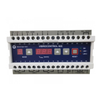
Fig.7.1
Auxiliary input/output
connections
Compatibility with Existing Type 7536 Controller Modules
• Type 7536 100 Mbit Controller modules, hardware version 12.0 and greater, are com-
patible and calibrated
• Type 7536, hardware version 11.02, and serial number 2352315 – 2352340 of hard-
ware version 12.0, are compatible but need recalibration
• Type 7536, hardware version 11.02, will not function properly without a simple hard-
ware modification. There is a risk of damage if these modules are used for auxiliary
logging without the modification
DC Out
Pins 10 and 20 are DC outputs that allow a simple on/off control to be used. The DC
outputs are open-drain outputs internally pulled up to + 5 V by 100 kΩ. Open-drain internal
current limit is 5 mA and the maximum external voltage is 24 V.
For example, you can use the outputs to trigger an alarm. If the alarm function in PULSE’s
Level Meter
a
is used to control a DC voltage from Aux. I/O, then:
10 9 8 7 6 5 4 3 2 1
DC 1 GND N.C. N.C. ch. 11 ch. 9 ch. 7 ch. 5 ch. 3 ch. 1
20 19 18 17 16 15 14 13 12 11
DC 2 5 V N.C. N.C. ch. 12 ch. 10 ch. 8 ch. 6 ch. 4 ch. 2
10 9 8 7 6 5 4 3 2 1
20 19 18 17 16 15 14 13 12 11
Front view
050182
a. For information on how to set an alarm, see “Level Meter Input Range” in the PULSE help
(click on Aux. I/O in the help index).

 Loading...