Translation of the Original Operating Instructions
VP-80/VP-80 E
54
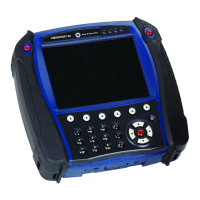
7 Operator Interface
This chapter provides a detailed overview of using the opera-
tor interface of the VIBROPORT 80 and the basic operating
concept.
The general mode of functioning implemented by the firmware
is also described.
7.1 Explanation of symbols
The symbols listed here are used in the operator interface of
the VIBROPORT 80 to indicate the status of the respective
function. This enables easy and intuitive operation.
Tab. 8 Explanation of symbols
Note!
The lists / settings in the operator interface are dynamic. The
relevant data are faded in depending on the selection made.
Picto-
gram
Explanation
Blue pictograms
Blue pictograms represent different measuring
modules or correspond to predefined measu-
ring tasks.
Gray pictograms
Gray pictograms represent measuring modu-
les which are already installed but have not yet
been activated or licensed.
Red pictograms
Red pictograms are assigned for help, new
non-predefined measuring tasks, reports, Sen-
sor Setup and System Setup.
 Loading...