Installation and Operation of the HTK-Series, TTK 600, XRK 900, and HPC 900 Chambers
DOC-M88-EXX268_V1_12.2016 51
5. Insert it by aligning the red dots on chamber and diffractometer and then rotating
clockwise.
Figure6.2: Red dots for the bayonet fixture in the “locked” position
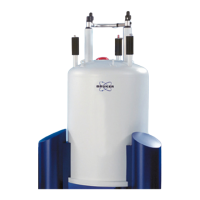
6. Fix the chamber mount using the three screw holes.
Figure6.3: Fixing screws for the TTK 600 adapter

 Loading...