Installation and Operation of the BTS 150 and BTS 500 Chambers
96 DOC-M88-EXX268_V1_12.2016
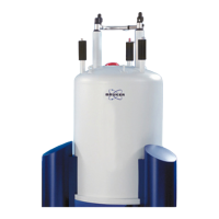
Figure9.1: Fixing screws for the BTS 150/500 adapter
5. Attach the chamber to the mount by inserting the micrometer screws in the back into
the designated holes in the mount.
6. Feed the heater power cable, the USB cable, and the vacuum/gas tubes (optional),
through the labyrinth.
If necessary, connect the vacuum tubes to a vacuum pump or to the desired gas source
(the chamber supports inert gases such as N
2
and He as well as air). The chamber takes
4mm gas or vacuum tubing that can be plugged directly into the connectors at the top of
the chamber (see figure above).

 Loading...