Do you have a question about the Brusa BSC624-12V-B Series and is the answer not in the manual?
Overview of technical abbreviations used in the manual.
Explanation of various symbols used for warnings and prohibitions in the manual.
Defines different danger levels (DANGER, WARNING, CAUTION) and associated risks.
Provides general safety guidelines for installation, operation, and accident prevention.
Details safety features like short-circuit protection, interlock, and overload protection.
Specifies qualifications and knowledge required for personnel performing start-up procedures.
Outlines the content, structure, and purpose of the technical manual.
Lists all necessary documents and software for successful device commissioning.
Details all components included in the product package with quantities and illustrations.
Describes the intended applications and operational environments for the DC/DC converter.
Specifies operating limits and conditions that constitute improper use and may cause damage.
Provides detailed electrical, mechanical, and thermal specifications of the device.
Highlights key features like compact design, vibration resistance, HV range, and galvanic isolation.
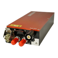
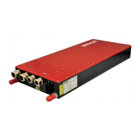
Illustrates the functional overview and main components of the DC/DC converter.
Explains the operational principles and electromagnetic compatibility aspects of the device.
Covers device dimensions, fixing points, and general installation guidelines.
Details the function of each pin on the control connector.
Specifies the pinout for the High Voltage power connector.
Details the pinout for the Low Voltage power connector.
Information on connecting and using the device's control connector.
Assembly instructions and safety precautions for the HV power connector.
Assembly instructions and guidelines for the LV power connector.
Instructions for establishing a secure LV and power ground connection.
Guidelines for connecting and venting the device's cooling system.
Step-by-step guide for preparing HV cables and connector glands.
Procedure for ensuring the cooling circuit is free of trapped air for optimal performance.
Explains the necessity and procedure for pre-charging loads before activation to prevent damage.
Guide to installing and using the PARAM software for device configuration.
Instructions for setting up the CVI CAN user interface for testing.
Describes how to operate the device using the CAN interface and control signals.
Details how to configure and operate the device autonomously without a CAN connection.
Lists the operating systems compatible with the Flash Development Toolkit.
Step-by-step guide for installing the necessary software for firmware updates.
Steps to prepare the device and PC before executing a firmware update.
Detailed procedure for updating the device's firmware using the development toolkit.
| Brand | Brusa |
|---|---|
| Model | BSC624-12V-B Series |
| Category | Media Converter |
| Language | English |