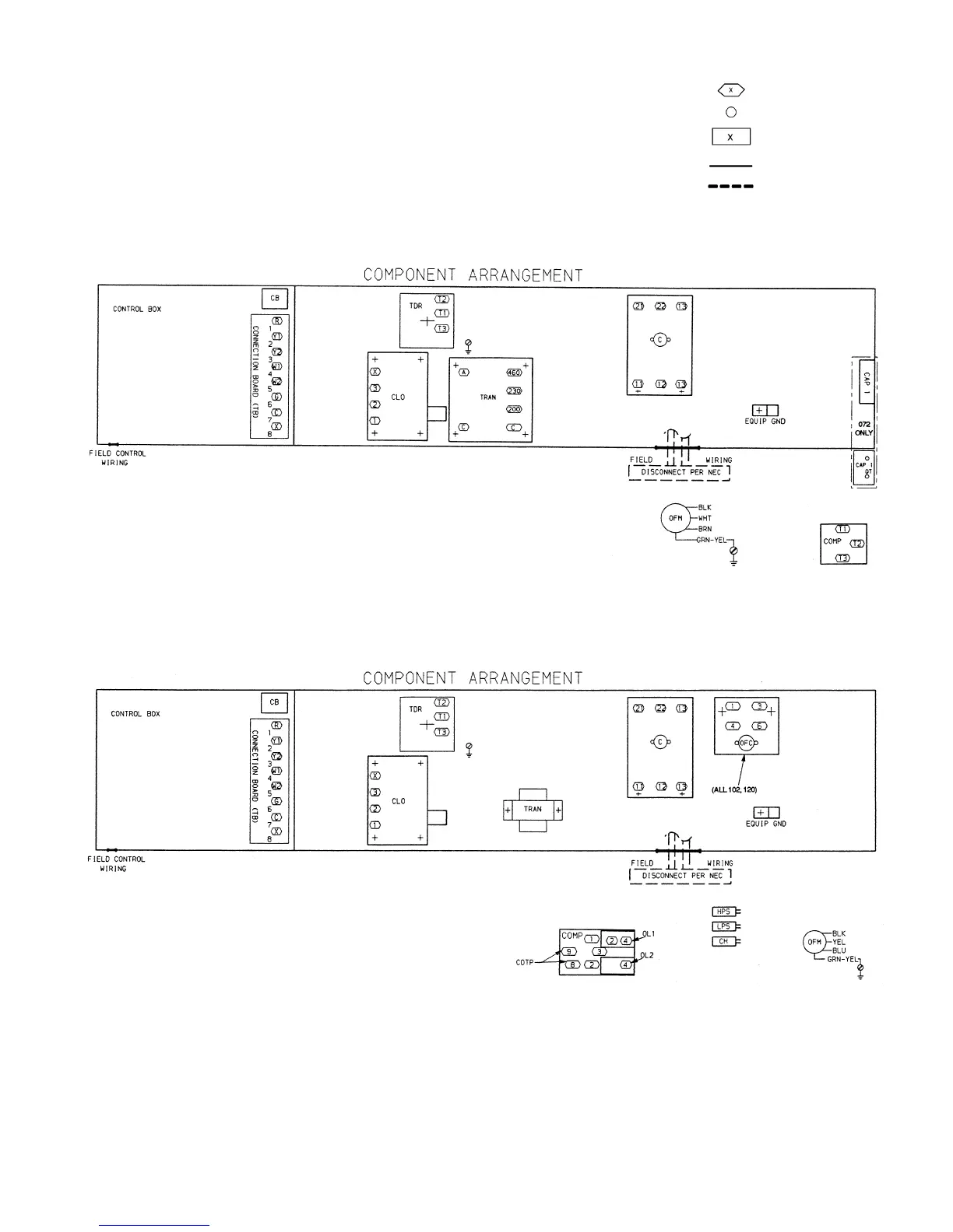
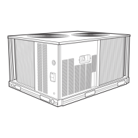
LEGEND FOR FIG. 16 AND 17
C—Contactor, Compressor
CAP — Capacitor
CB — Circuit Breaker
CH — Crankcase Heater
CLO — Compressor Lockout
COMP — Compressor Motor
COTP — Compressor Temperature Protection
EQUIP — Equipment
GND — Ground
HPS — High-Pressure Switch
LPS — Low-Pressure Switch
NEC — National Electrical Code
OFC — Outdoor (Condenser) Fan Contactor
OFM — Outdoor (Condenser) Fan Motor
OL — Overload Relay
QT — Quadruple Terminal
TB — Terminal Block
TDR — Time-Delay Relay
TRAN — Transformer
Terminal (Marked)
Terminal (Unmarked)
Terminal Block
Factory Wiring
Field Power Wiring
Fig. 16 — Typical 569C Wiring Schematic and Component Arrangement
Fig. 17 — Typical 576B Wiring Schematic and Component Arrangement
—15—