8.2 Cut down installation plate installation
8.2.1 Reduced installation plate.
8.2.2 The installation plate is recommended to be supplied ‘factory cut. All four sides can be supplied cut down
where required.
8.2.3 A length of steel supporting angle should be affixed to the top of the opening as shown in fig. 5
8.2.4 The damper should be installed within and affixed to the top supporting angle.
8.2.5 Fire batt material should be cut to suit void with zero clearance to produce an interference fit. The
installation
plate face, and all edges should be ‘glued’ in place, and a bead of intumescent mastic applied at all joints.
8.2.6 Note – two layers of 50mm min thickness are required to comply with the ‘as tested’ installation method.
8.2.7 Screw-in 50mm long spiral (pig tail) fixings through installation plate into batt material utilising one of the pair
of corner holes, and all intermediate fixing holes. (It may be necessary to drill additional fixing holes
depending on plate size reduction).
8.2.8 Recommended minimum void gap (per side) is 40mm and maximum 600mm.
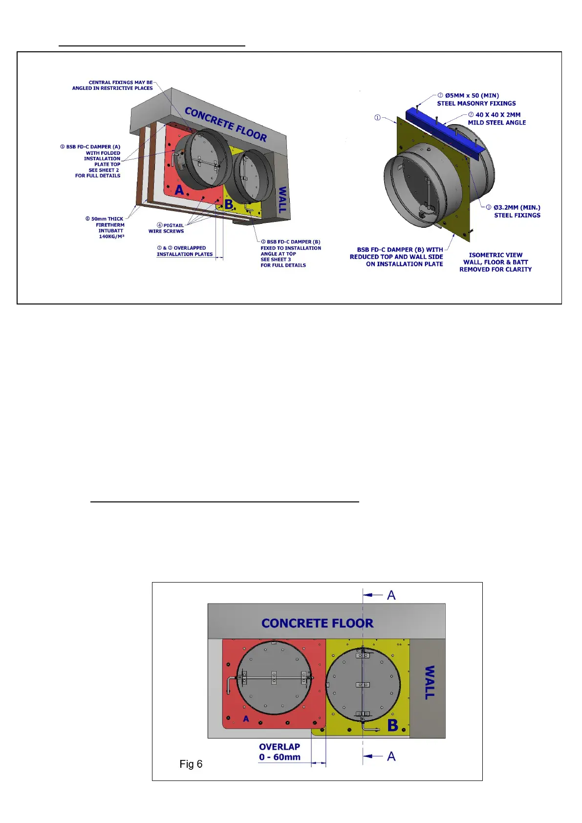
8.3 Overlapping installation plate installation (refer to fig 6)
8.3.1 It is permissible to overlap the installation plate with another installation plate where two dampers are near to
each other.
8.3.2 The two overlapping plates should be secured together by drilling 3.2mm dia holes and using steel rivets
mirroring the existing fixing pitches.
8.3.3 Screw-in 50mm long spiral (pig tail) fixings through installation plate perimeter into batt material utilising one of
the pair of corner holes, and all intermediate fixing holes
 Loading...