6
Installation
22/39 ekr 500 digital Unit Touch – Application with Wide Array Edge Sensors
6.3 Installing the Connection Box
6.3.1 Selecting the Installation Location
DANGER
Danger of death when operated in potentially explosive areas!
►
The system must not be installed or operated in potentially
explosive areas.
In addition to the basic ambient conditions (see Connection Box,
page 18), the following conditions also have to be fulfilled:
■ Installation location dry, vibration-free and level
■ Minimum clearance of 100 mm to electro-magnetic fields
(energy sources or high voltage lines)
■ No sources of heat in the immediate vicinity
■ Distance between the connection box and the wide array edge
sensor not more than 600mm (limited by the connecting cable
length)
6.3.2 Installing the Connection Box
NOTICE
Damage to the system from drilling dust and loose parts!
Drilling dust, splitter and loose parts may damage the machine.
►
Before carrying out drilling or installation work, cover the
affected area of the machine with film or paper.
►
After installation work, check that the bolts are screwed tight.
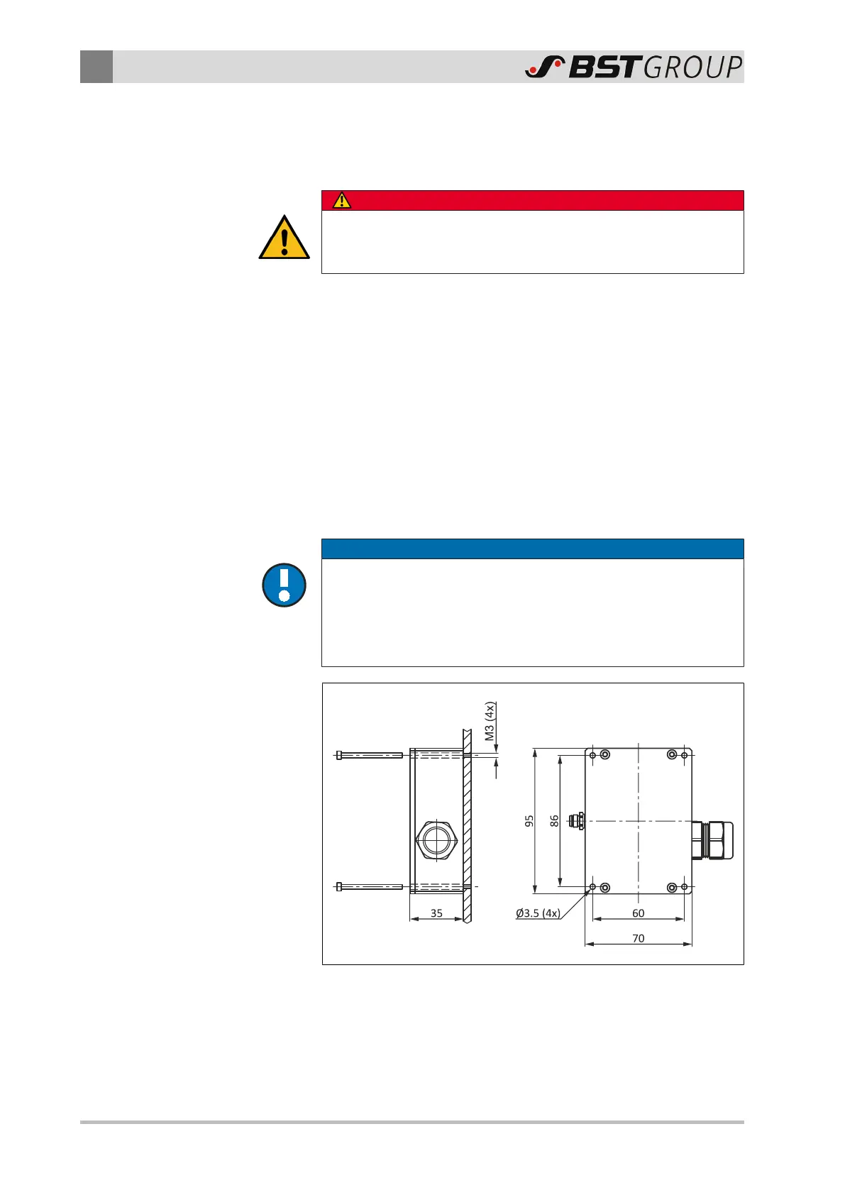
Fig.8: Installation of the connection box
1. Add the threaded boreholes M3 to the machine frame accord-
ing to the picture.
2. Using four screws M3, attach the connection box to the
machine frame.
 Loading...


