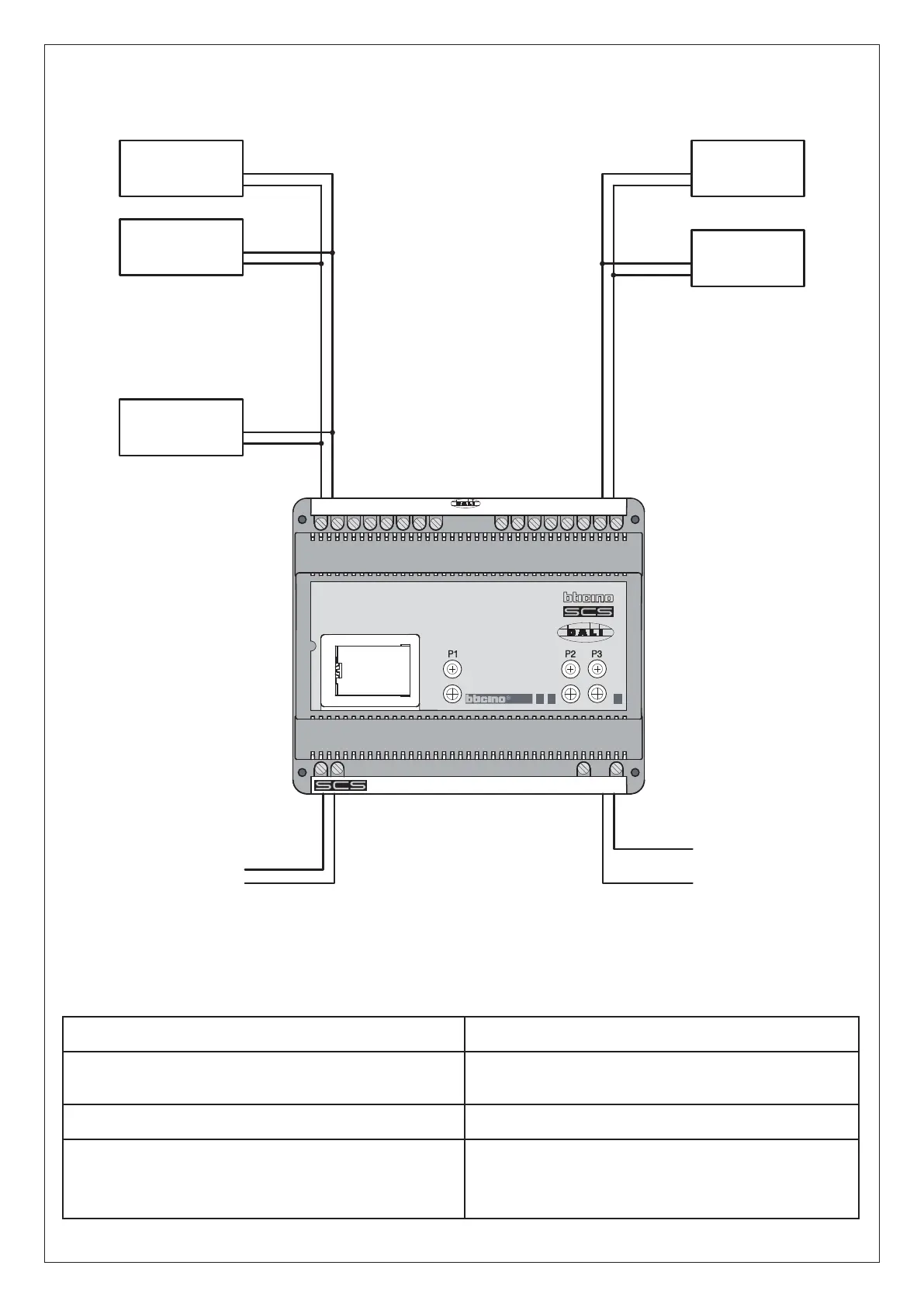
MAX 16
DEVICES FOR
OUTPUT
DALI
DEVICE
DALI BUS
L
N
SCS BUS
OUTPUT 1 -- --- ---- ---- OUTPUT 8
DALI
DEVICE
DALI
DEVICE
DALI
DEVICE
DALI
DEVICE
-- --
L
N
8
7
6
5
_
+
_
+
_
+
_
+
4
3
2
1
_
+
_
+
_
+
_
+
OUTPUT
12
Wiring diagram
Modes of operation
The actuator performs all the basic modes of operation which can be configured directly on the control, apart from those which use interlocking
relays. The following table lists the functions which can be performed with the configurator inserted in position M of the same actuator.
Possible functions Configurator position M
Actuator as Slave. Receives a command sent from a master actuator
with the same address.
SLA
The actuator ignores the Room and General commands.
PUL
Master Actuator with OFF command delayed on the corresponding
slave actuator. Only for point-point command.
With the OFF command the Master actuator deactivates: the Slave ac-
tuator deactivates after the configured time has elapsed.
1=1 min
2=2 min
3=3 min
4=4 min