Installation (for engineers only)
Logamatic SC40 - Technical specifications are subject to change without prior notice.
30
4
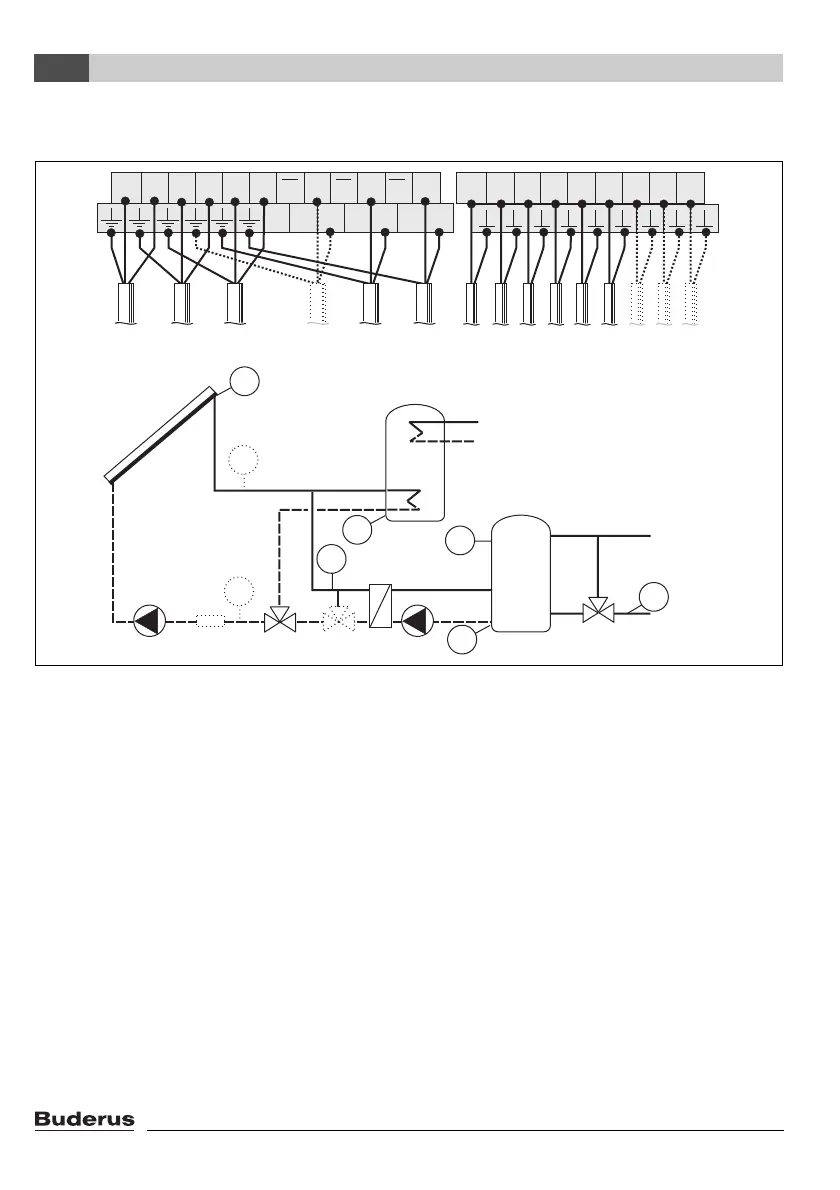
4.4.18 Configuration diagram H8 - heating boost system with 2 cylinders connected via
valve and external heat exchanger
Fig. 24
R1 Solar circuit pump 1
R2 Heat exchanger pump
R3 Anti-icing system valve (optional)
R4 Cylinder selection valve
R5 Return flow boost valve
S1 Collector temperature sensor FSK
S2 Cylinder 1 bottom temperature sensor
S3 Heating return temperature sensor
S4 Temperature sensor for external heat exchanger
S5 Cylinder 2 bottom temperature sensor
S6 Cylinder 2 top temperature sensor
S7 Flow heat meter WMZ temperature sensor (optional)
S8 Return heat meter temperature sensor (optional)
WMZ Heat meter (optional)
WMZ
R1
S2
S3
S6
S8
S7
R5
S1
R4
S5
R2
S4
R3
7747006072-17.1 SD
S1 S2 S3 S4 S5 S6 S7 S8 I9
L N R1N1R2N2R3R3R4R4R5R5
L3 N3 L4 N4 L5 N5
230V
AC
R4
R3
R5R2R1
S1 S2 S3 S4 S5 S6 S7 S8
WMZ
 Loading...
