EasyManua.ls Logo

Build RC 3M Gliderman - User Manual

Build RC 3M Gliderman
13 pages
Print Icon
To Next Page IconTo Next Page
Loading...
3M Gliderman
1
To finish, you still need the following accessories:
• Remote control unit with receiver (5 channels)
• 4x servo D-200 BX (or D-250 BX with metal gears)
• Motor DYMOND AL-4260
• 60-amp motor controller
• 5S LiPo battery with 5000 mAh
• 14 x 6 prop, spinner diameter 45 mm
• Servo Extensions
• MPX connector for tail servo cable
• Superglue liquid medium
• Epoxy e.g. 5-minute epoxy
• Rudder Horn, INSTRUCTIONS. 03150100, 1x M2 clevis, threaded coupler M2, a little
spring steel wire 1.5 mm
Question and Answer IconNeed help?

Do you have a question about the Build RC 3M Gliderman and is the answer not in the manual?

Overview

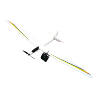
The 3M Gliderman is an electric glider model designed for remote control enthusiasts. This manual provides instructions for assembling and setting up the glider, including details on required accessories, tail and wing completion, drive installation, and flight preparation.

Function Description:

The 3M Gliderman is a high-performance electric glider designed for enjoyable flight experiences. It is powered by an electric motor and controlled via a 5-channel remote control unit. The model is intended for safe and controlled flight, with specific instructions provided for assembly, setup, and initial flight procedures to ensure optimal performance and safety. The glider's design emphasizes a balance between lightweight construction for efficient gliding and robust components for durability.

Important Technical Specifications:

Required Accessories (to be purchased separately):

  • Remote Control Unit: 5-channel receiver and transmitter.
  • Servos: 4x D-200 BX (or D-250 BX with metal gears) servos for elevator, rudder, and ailerons. The D-200 BX servos are recommended for weight saving in the tail, though D-250 BX with metal gears offers greater durability but may require additional nose weight.
  • Motor: DYMOND AL-4260.
  • Motor Controller: 60-amp.
  • Battery: 5S LiPo battery with 5000 mAh (e.g., DYMOND XC-5000 5S). This large capacity battery helps balance the model due to the relatively heavy tail.
  • Propeller: 14 x 6 prop with a spinner diameter of 45 mm.
  • Servo Extensions: For connecting servos to the receiver.
  • MPX Connector: For the tail servo cable, and optionally for outer wing aileron servos to facilitate comfortable assembly/disassembly.
  • Adhesives: Superglue (liquid medium) and 5-minute epoxy.
  • Rudder Linkage Components: Rudder Horn (Article No.: 03.1501 million), 1x M2 clevis, threaded coupler M2, and 1.5 mm spring steel wire.

Control Surface Deflections and Center of Gravity (C.G.):

  • Ailerons: 20mm measured inside.
  • Elevator: 15 mm measured at the leading edge.
  • Rudder: As much as possible.
  • Focus (C.G.): 75-90 mm measured from the leading edge of the wing. The C.G. is adjusted by shifting the drive battery.

Usage Features:

Tail Completion:

  • Servo Installation: Elevator and rudder servos are built directly into the vertical stabilizer. Lightweight servos (D-200 BX) are recommended to save weight in the tail, although metal gear servos (D-250 BX) offer greater durability at the cost of potential nose weight requirements.
  • Linkage Setup: The elevator linkage is set in the second hole from the inside on Dymond D-200/250 BX servos. The rudder pushrod is set in the third hole from the inside. A 2.5 mm hole needs to be drilled for the elevator pushrod.
  • Servo Mounts: Pre-servo mounts need to be reworked with a cutter to fit the servo contours.
  • Rudder Linkage Assembly: The rudder linkage involves a control horn, a crown, and an M2 threaded coupler with a soldered 1.5mm steel wire. A 4mm hole is drilled in the rudder for the control horn, which is then epoxied into place. This process requires careful execution due to limited material.
  • Servo Cable Extension: Servo cables need to be extended, preferably with MPX connectors for a solid connection during installation.
  • Elevator Pushrod: The elevator pushrod is mounted in the second hole of the servo output arm (drilled to 2.5 mm) and requires no additional fixing. The servo arm should be ground down to prevent scratching the cover.
  • Servo Security: The elevator servo is secured by a wooden cover. The rudder servo is held in place by a plastic cover, which requires drilling holes (1.5 - 2.5 mm) and cutting for the rudder. A template for the rudder cover is provided. For weight reasons, replicating the cover with 0.3 mm thick PS or ABS is suggested.
  • Elevator Halves: The two halves of the elevator are typically glued together. A removable solution can be implemented in-house if desired.

Wing Completion:

  • Aileron Hinges: Ailerons are hinged with supplied parts. The horns serve as a template for drilling three 1.5 mm holes in the rudder area. Volatile pushrods are recommended.
  • Aileron Servos: Aileron servos are secured in the shafts with included wood pieces, similar to the elevator servo. The mounting frame may need modification with a mill. Power cord extensions can be used, and MPX connectors are recommended for outer wings for ease of assembly/disassembly.
  • Wing Attachment: Outer wings are secured with tape by default, but a more complex solution can be realized.
  • Servo Covers: Covers for the aileron servos are also secured with tape.

Drive Installation:

  • Motor Power: The DYMOND AL-4260 motor with a 14x6 prop and 5S LiPo battery (18.5V) provides significant power for safe and powerful starts.
  • Battery Placement: A large 5000 mAh battery helps balance the model due to its heavy tail.
  • Cable Management: Ensure motor cables do not rub against the rotating casing of the engine. Secure cables with tape inside the fuselage.
  • Controller Placement: The spacious boat hull allows the controller to be placed next to the battery.
  • Hood Attachment: The model's hood is attached with tape, though a spring steel wire can be glued in for a more secure fit.

Assembly and First Flight:

  • Fuselage Assembly: The two fuselage parts are secured with tape, ensuring a secure fit due to their conical shape. More complex solutions can be implemented if desired.
  • Wing Assembly: The wing is assembled using the wing joiner and plastic screws to attach it to the fuselage. Ensure power cables are not pinched.
  • Receiver Connections: Connect the aileron cable to the receiver according to the remote control system instructions. Connect the motor controller to the motor as per manufacturer's instructions.
  • C.G. Adjustment: With the flight battery installed, determine the center of gravity (75-90 mm from the leading edge). The model should be supported with one finger on each side of the wing at the marked centroid. The model is properly balanced when it settles with a slightly tilted nose. The C.G. can be finely adjusted by shifting the drive battery.
  • First Flight Conditions: The first flight should be conducted on a windless or slightly windy day.
  • Launch Procedure: Start the model with the engine running, launching against the wind with a flourish. The engine should provide sufficient power for a good climb at a medium angle.
  • Trim Adjustments: Slight trim adjustments may be required during the initial flight.
  • Gliding: After switching off the engine, the model should continue to fly horizontally at a slower rate.

Maintenance Features:

General Maintenance:

  • Film Retightening: Before construction, it may be necessary to retighten the film with a heat gun or iron. Exercise caution around aileron hinges as the hinge material is not heat-sensitive, but the covering can curl.
  • Wing Covering: Ensure the covering remains stuck to the ribs on the concave underside of the wing to maintain the profile.
  • Regular Checks: Always check the function of the rudder and all components before each flight.
  • Adhesive Use: Use superglue and epoxy as specified for secure component attachment.

Safety Notes:

  • Safety Conscious Flying: Always fly with safety in mind. Pilots of flight models bear significant responsibility.
  • Model Familiarization: Understand your model's capabilities and how it responds to controls.
  • Rudder Adjustment: If the rudder is adjusted according to instructions, the model will react softly to control commands.
  • Not a Toy: This model is not a toy. Inexperienced users of electrically powered models should seek assistance from experienced model flyers. Improper operation can cause injury.
  • Pre-Construction Reading: Read all instructions thoroughly and familiarize yourself with each phase of construction before starting.
  • Safety Instructions: These safety instructions are part of the manual and must be stored carefully and passed on to subsequent users.
  • Intended Use: Radio-controlled models should only be used for their intended purpose as specified by the manufacturer.
  • Proper Assembly: The model will only perform correctly and meet expectations if built and installed carefully according to the instructions.
  • No Unauthorized Modifications: Unauthorized modifications to the design or materials are not permitted.
  • Control Surface Observation: Pay close attention to the information regarding control surfaces.
  • Frequency Check: Before turning on the remote control, ensure your frequency is clear.
  • Responsibility: The user is solely responsible for the safe operation of the model and engine.
  • Propeller Safety: Propellers and all rotating parts driven by the motor pose a risk of injury. Avoid touching any body part; a rapidly rotating propeller can cause severe injury.
  • Liability: The company (LEADERS) assumes no liability for any loss, damage, or expense resulting from faulty operation, faulty behavior, or any connection to the foregoing, unless legally required. The company's obligation to pay damages for any reason is excluded.

Build RC 3M Gliderman Specifications

General IconGeneral
BrandBuild RC
Model3M Gliderman
CategoryToy
LanguageEnglish