Page 18
.
MINUTE
S
BUNN-O-MATIC
P/N 26
20- 120 VAC
.
MINUTES
BUNN-O-MATIC
P/N 2620- 120 VAC
STA
RT
ON / WARMER
SELECTOR
READY
READ
Y
ON / WA
RMER
START
1
1⁄2
gal1 ga
l
1⁄2
gal
SELECTOR
1
1
⁄
2
g
al1 gal
1⁄
2
ga
l
CA U
T
I
ON :
W
AR ME R
S
AN D SU
RF AC E
S AR E
H
O
T
P796
Location:
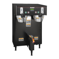
Dispense valves are located inside the hood in the
center of each sprayhead panel.
Test Procedures:
1. Disconnect the brewer from the power source.
2. Disconnect the wires from the right dispense valve
and check the voltage across the white/violet wire
and white/green wire. Connect brewer to the power
source. Place the "ON/OFF" switch in the "ON"
position, press and release the start switch. The
indication must be:
a.) 120 volts ac for two wire 120V models, three
wire 120/208 volt models and three wire 120/240
volt models.
b.) 200 to 240 volts ac for two wire 200 or 240
volt models.
3. Disconnect brewer from the power source.
4. Disconnect the wires from the left dispense valve
and check voltage across the white/red wire and
the white/brown wire. Connect the brewer to the
power source. Place the "ON/OFF" switch in the "ON"
position and press and release the start switch.
The indication must be:
a.) 120 volts ac for two wire 120V models, three
wire 120/208 volt models and three wire 120/240
volt models.
b.) 200 to 240 volts ac for two wire 200 or 240
volt models.
5. Disconnect brewer from power source.
FIG. 11 DISPENSE VALVE
P780
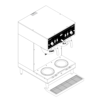
FIG. 10 CONTROL THERMOSTAT
TERMINALS
BLU to Ready Light(s)
BLU to Overflow Protection Switch
BLKtoBLKLeadofContactorCoil
BLKtoReadyLight(s)
NOTE - The capillary tube must be clear of any electri-
cal termination and not kinked.
7. Using a #8-32 slotted head screw fasten the control
thermostat to the component bracket.
8. Refer to Fig. 10 when reconnecting the wires.
9. Adjust the control thermostat as required.
SERVICE (cont.)
CONTROL THERMOSTAT (cont.)
DISPENSE VALVE
41976 031709
 Loading...