Page 28
SERVICE (cont.)
RED
BLK to BLK Lead on
Contactor Coil
BLK to BLK Lead on
Thermostat
WHI/RED to Left Dispense Valve
WHI/BRN to Left Dispense
Valve
WHI/GRN to Right Dispense
Valve
BLU to BLU Lead
from Thermostat
BLU to BLU Lead
from Liquid Level Board
WHI/VIO to Right Dispense
Valve
RIGHT
LEFT
BREWERS W/RECOVERY BOOSTER
B
A
A
7
7
5
5
B
P1378
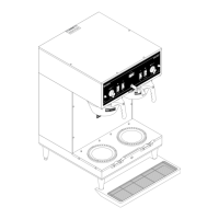
FIG. 31 RECOVERY BOOSTER RELAYS
Relay (Brewers W/Recovery Booster) (cont.)
and white/red wire from "B" terminal on the left
relay.
6. Check for continuity across the "A" and "B" terminals
of each relay.
If continuity is present as described, reconnect the
white /green wire and white/violet wire to the right
relay or the white/brown and the white /red wire to
the left relay and proceed to #7.
If continuity is not present as described, replace the
relay(s).
7. Remove the two blue wires from terminal 5 and
the red wire from terminal 7 on the right relay, the
black wires from terminal 5 and the red wire from
terminal 7 on the left relay.
8. Check for continuity across terminals 5 and 7
of each relay by manually closing relay contact.
Continuity must not be present when contact is
released.
If continuity is present as described, reconnect blue
wires to terminal 5 on the right relay, the black wires to
terminal 5 on the left relay and the red wire to left and
right terminal 7, the relays are operating properly.
If continuity is not present as described, replace the
relay(s).
Removal and Replacement:
1. Remove all wires from relay terminals.
2. Remove the #6-32 truss head screw securing relay
to the relay mounting bracket.
3. Remove the relay and discard.
4. Securely install the new relay to the mounting
bracket using a #6-32 truss head screw.
5. Refer to Fig. 31 when reconnecting the wires.
41976 031709
 Loading...