Page 35
START ON / WARME
R
SELECTOR
READY
READY
ON / WARMER
START
1
1⁄2
gal
1
gal
1
⁄
2
ga
l
SELECTOR
1
1⁄2
gal
1 gal
1⁄2
gal
P792
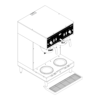
Location:
The momentary start switches are located on the
front of the hood next to the on/off switches.
Test Procedure:
1. Disconnect the brewer from the power source
and remove the wires from both terminals of the
switch.
2. Check for continuity across the two terminals on
the switch when it is held in the lower position.
Continuity must not be present across these ter-
minals in the upper position.
If continuity is present as described, reconnect the
wires, the switch is operating properly.
If continuity is not present as described, replace the
switch.
Removal and Replacement:
1. Remove wires from the switch terminals.
2. Compress the clips inside the hood and gently
push the switch through the opening.
3. Push the new switch into the opening and spread
the clips to hold the switch in the hood.
4. Refer to Fig. 39 when reconnecting the wires.
P801
FIG. 38 START SWITCHES
ORN to Left Timer TL3 (Electro/
mechanical)
RED/BLKtoInterlockAssy(Elec-
tronic)
YEL to Left Timer TL5
WHI/ORN to Right Timer TL3 (Elec-
tro/mechanical)
BRN/BLKtoInterlockAssy(Elec-
tronic)
WHI/YEL to Right Timer TL5
P1386
FIG. 39 START SWITCH TERMINALS
WHI/VIO to ON/OFF Switch
and Brew Timer TL1
GRN to Server
Power Relay "A"
WITH RELAY (Prior to S/N SNG0014000)
WITHOUT RELAY(After S/N SNG0014000)
BLKToSHTrans-
former #1
BLKtoOn/Off
Switch
WHI/YEL to
Timer #5
WHI/ORG to
Timer #3
SERVICE (cont.)
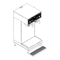
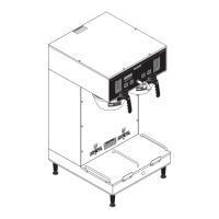
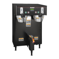
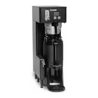
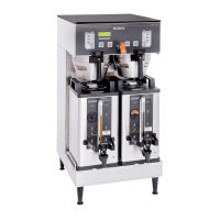
START SWITCHES
DUAL BREWERS
SINGLE BREWERS
41976 031709
 Loading...