Page 45
If continuity is not present as described, replace the
switch.
Removal and Installation:
1. Disconnect the wires from the switch terminals.
2. Remove the two screws securing the switch to the
base plate from the bottom side of the brewer.
3. Position the new switch into the opening in the base
plate and secure with the two mounting screws.
4. Refer to Fig. 51 when reconnecting the wires.
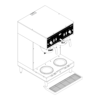
Location:
The MAIN ON/OFF switch is located in the base
housing behind the right front leg.
Test Procedure:
1. Disconnect the brewer from the power source.
2. Remove the red wires from the terminals.
3. Check the voltage across the red wires with a volt-
meter. Connect the brewer to the power source.
The indication must be 120 volts ac.
4. Disconnect the brewer from the power source.
If voltage is present as described, reconnect the red
wires, and repeat steps 2 and 3 for the black wires.
If voltage is not present as described, refer to the Wiring
Diagrams and check the brewer wiring harness.
5. With the red and black wires removed, check for
continuity across the right terminals and across
the left terminals with switch in the "ON" position.
Continuity must not be present when switch is in
the "OFF" position.
If continuity is present as described, reconnect the red
and black wires to the terminals.
SERVICE (cont.)
MAIN ON/OFF SWITCH
FIG. 50 MAIN ON/OFF SWITCH
P973
FIG. 51 MAIN ON/OFF SWITCH TERMINALS
P3953
Black wires from
Terminal Blocks
Red wires from
Terminal Blocks
41976 031709
 Loading...