www.bvmsystems.co.uk
sales@bvmsystems.co.uk
40-0287-12
- 14 -
Appendix IV
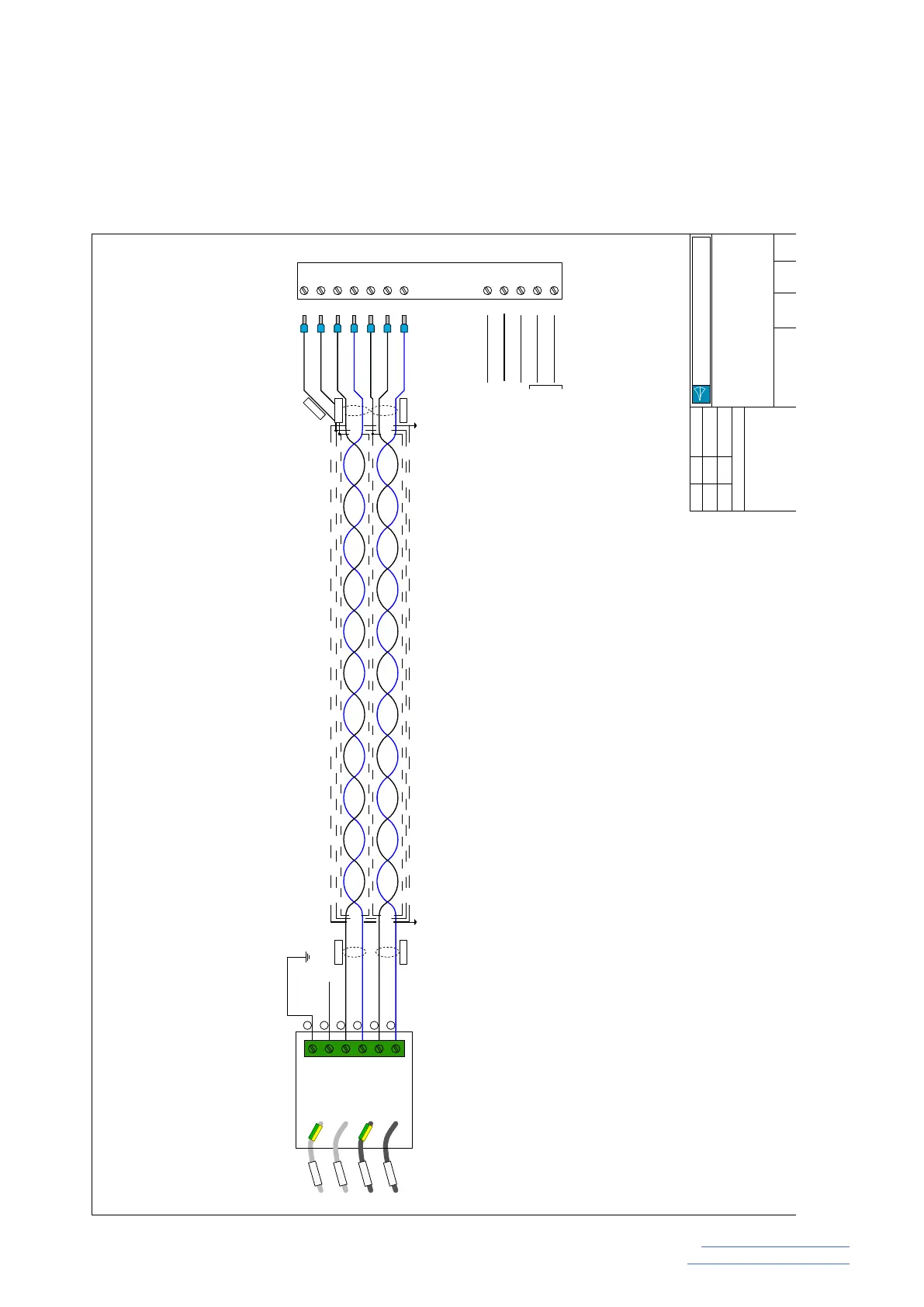
PQSensor Wiring Diagram
Test
HCCT
LCCT
HCCT
LCCT
HCCT1
HCCT2
LCCT1
LCCT2
Measurement
Unit
Test
Black
Blue
Black
Blue
1
2
3
4
5
6
10
11
12
13
14
15
16
3
4
5
1
2
PQSensor SCM
TB1
Black
Blue
White
Black
Blue
White
Black
Supply 1
Supply 2
110/230Vac
100-250Vdc
(not polarity
sensitive)
Earth
Output
Output Common
Cable armour grounded
by cable gland
Cable armour grounded
by cable gland
Armour
Collective Screen
Indivdual Screen
Earth
Note
SCM terminal 3 must always be connected to ground
MU terminal 6 must always be grounded
MU terminal 5 should be unconnected when the PQSensor
is in service
No other connections are required on TB1
Date
App:-
Rev:-
Details:-
Ckd:-
Sign
Additional details added
JM
MW
30.09.19
30.09.19
06
BVM Drawing No.:- Sheet :- of
Title:-
BVM Systems Limited
BVM Systems
Size
PQSensor MkVI Wiring Details
 Loading...