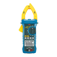
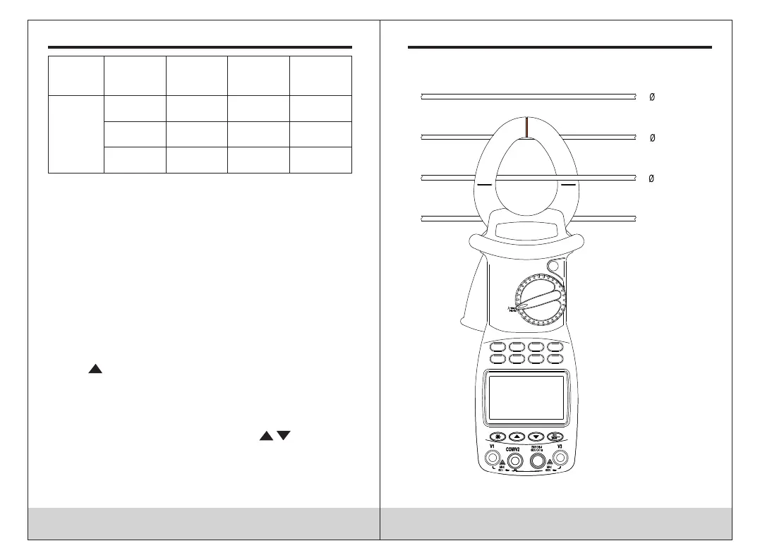
Position
Input
terminal V1
Input
terminal V2
Input
terminal V3
Object
under test
V~
Toma V1
Toma V2/
COM
N/A Monofásico
Toma V1
Toma V2/
COM
N/A Bifásico
Toma V1
Toma V2/
COM
Toma V3 Trifásico
1. According to the connection mode indicated in the table
above, place the thumbwheel in the V ~ position, select the
corresponding sockets for the V1, V2 or V3 terminals and
insert the test leads.
2. Connect the two test leads V1, V2 to the power source or
load to be tested. The clamp will automatically perform the
measurement and display the result on the screen and the
percentage of harmonics present will be shown on the next
line.
3. In the voltage measurement function, press the SET key
to display “AUTO V” and “AUTO A” on the display and press
the key to select the appropriate voltage scale and
press SET again to return to normal mode.
4. Press the MODE key to show the harmonic percentage
on the screen and the total harmonic distortion ratio F and R
will be displayed cyclically. Press the keys to display
the value of each harmonic.
5. When the input voltage is higher than 50V, the symbol ()
will be displayed on the screen, warning of the risk.
13
AC current measurement (A)
14
3
2