Input Impedance: 10MΩ
Max. Input Voltage: 1000V DC or 750V rms AC
- By μA, mA or A range:
Frequency response: 0 ~ 40kHz
Input current range: ≥1/4 of the rms AC for the range
(higher input voltage at higher frequency)
- Max. input current:
mA jack(μA ranges): 4mA,
mA jack(mA ranges): 400mA,
10A jack: 10A
- Overload protection:
μA、mA ranges: resettable fuses F1 500mA/250V
10A range: F2 10A/250V fuse (quick acting).
NOTE:
The range by DUTY of the Hz range is larger than that of the
voltage range or current range.
3.2.9 Relative Humidity(on RH and humidity display)
Range Resolution Accuracy
20 - 95% 0.1% ± 5.0%RH
- Operating temperature: 0℃ to 40℃
- Sampling Period: ~20s.
- 20 -
DIGITAL MULTIMETER
SPECIFICATION
3.2.10 Temperature
3.2.10.1 Temperature(on sensor, thermoresistor NTC and
temperature display)
Range Resolution Accuracy
℃ 0.1℃ 0℃ to 40℃ ± 2℃
℉ 0.1℉ 32℉ to 104℉ ± 4℉
- Sampling Period: ~20s.
3.2.10.2 Temperature(on sensor, thermocouple and main
display)
Range Resolution Accuracy
-20℃ to 0℃ ± 5.0% of reading or ± 3℃
℃ 1℃ 0℃ to 400℃ ± 1.0% of reading or ± 2℃
400℃ to 1000℃ ± 2.0% of reading
-4℉ to 32℉ ± 5.0% of reading or ± 6℉
℉ 1℉ 32℉ to 752℉ ± 1.0% of reading or ± 4℉
752℉ to 1832℉ ± 2.0% of reading
- Overload protection: resettable fuses F1 500mA/250V.
3.2.11 Sound Level(dB)
Range Resolution Accuracy
40-100dB 0.1 dB ± 3.5%dB at 94dB, 1kHz sine
wave
- Typical instrument frequency range: 100 ~ 8000Hz
- 21 -
DIGITAL MULTIMETER
SPECIFICATION
3.2.12 Luminance(Lux)
RangeRange Res on Accuracy
Lux (4000) 1 Lux
×10Lux
(40000)
10Lux
±(5.0% of reading + 10 digits)
at color temp. 2856K calibrated to
standard incandescent lamp
- Re eatability: ±2%.
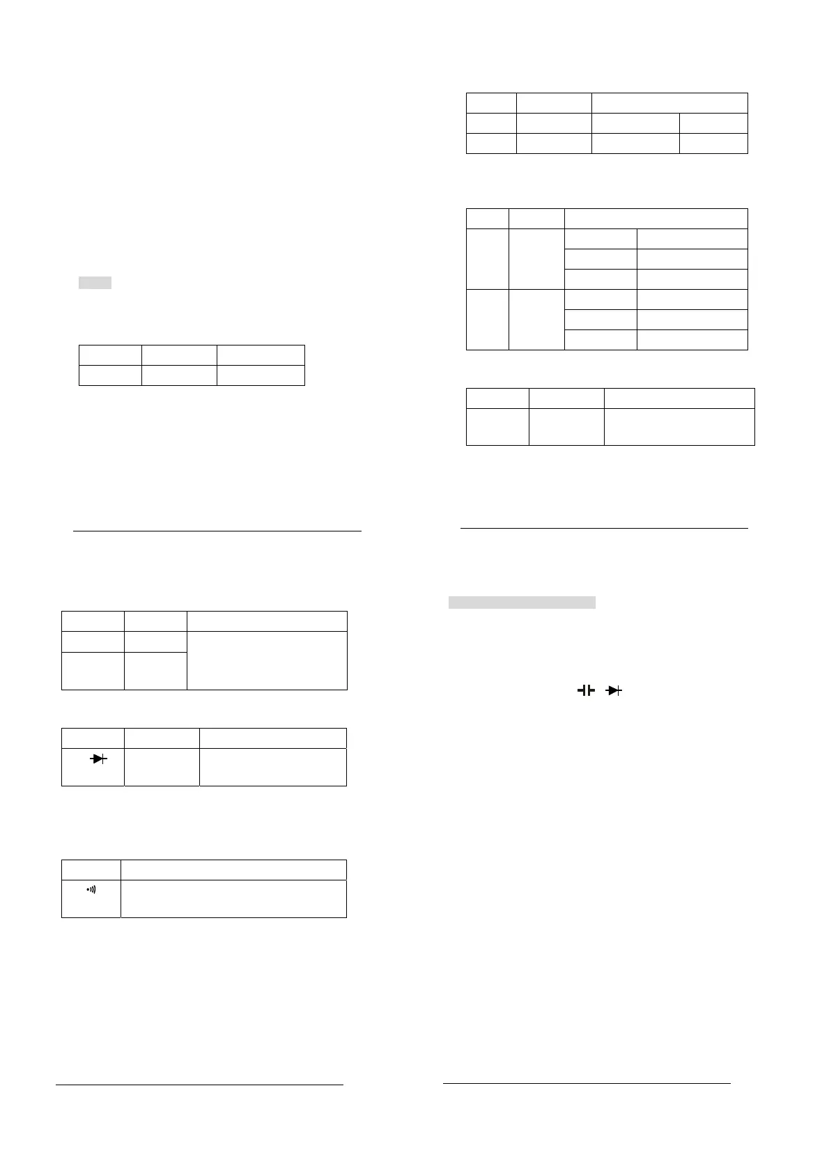
3.2.13 Diode Test
Rangee esolution Function
1mV displaying approximate
forward voltage of diode
- Forward DC current ~1mA
- Reversed DC voltage ~1.5V
- verload Protection: 250V DC or rms AC
3.2.14 Continuity Test
Range unction
Built-in buzzer will sound if resistance is lower
than 40Ω.
- pen circuit voltage ~0.5V
- verload Protection: 250V DC or rms AC
- 22 -
DIGITAL MULTIMETER
OPERAT INSTRUCTIONING
4.. ERATING INSTRUCTION
4.1 MISCONNECTION ALARM
The input jacks of the meter are equipped with sound and
light alarms against misconnection of test leads.
4.1.1 At V、Ω、Hz、Duty、 、 ranges:
1)The red lights at the “IN” and “COM” jacks will be off
after the test leads are plugged in.
2)The buzzer will sound upon misconnection of the test
leads in the “mA” or “10A” jacks to warn the user. At
the same time, the lights at the “IN” and “COM” jacks
will flash to remind the user to plug in the test leads
there.
4.1.2 At μA、mA, TEMP ranges:
1)The red lights at the “mA” and “COM” jacks will be off
after the test leads are plugged in.
2)The buzzer will sound upon misconnection of the test
leads in the “IN” or “10A” jacks to warn the user. At
the same time, the red lights at the “mA” and “COM”
jacks will flash to remind the user to plug in the test
leads there.
4.1.3 At 10A range:
1)) e red lights at the “10A” and “COM” jacks will be off
after the test leads are plugged in.
2)) he buzzer will sound upon misconnection of the test
leads in the “IN” or “mA” jacks to warn the user.
- 23 -
DIGITAL MULTIMETER
OPERAT INSTRUCTIONING
 Loading...