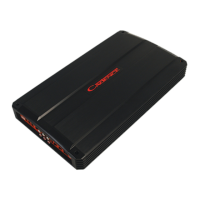
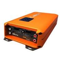
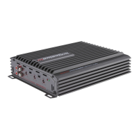
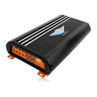
This document is an owner's manual for the Cadence FXA Series amplifiers, providing essential information for installation, operation, and maintenance. The Cadence FXA Series amplifiers are designed to deliver high-quality audio reproduction in car sound systems, building on years of technological advancement in amplifier design. The manufacturer emphasizes their commitment to producing powerful, reliable, and best-performing amplifiers, backed by an exclusive two-year warranty.
The manual begins by thanking the user for their purchase and highlighting the continuous innovation in Cadence amplifier technology. It notes that Cadence has a long history of satisfied customers, with some still using their first-generation Ultra Drive amplifiers from over 19 years ago. Unlike competitors who might stick to older designs, Cadence aims to develop the latest technologies to provide the best-sounding and most powerful amplifiers at a reasonable price. The manufacturer assures users that they will be "Boom-Harder!" with the FXA Series amplifiers due to the rugged, reliable, powerful, and high-performing design.
Users are strongly advised to read the entire installation guide carefully before attempting any installation. For technical assistance during or after installation, a technical support line is provided, available Monday through Thursday from 9:30 AM to 5:00 PM EST, along with a toll-free number.
A critical warning is issued regarding the use of the amplifier at extreme high volumes for extended periods, as this can cause hearing loss or damage. During prolonged high volume levels, the use of ear safety devices is recommended. The manual also cautions that playing Cadence amplifiers at high volumes while driving can impair the ability to hear necessary traffic sounds, urging users to keep sound volume at reasonable levels for safety. The manufacturer expresses a desire for users to enjoy their listening experience for many years.
When installing the amplifier, it is crucial to secure it tightly. An unmounted amplifier can cause serious injury to passengers and damage to the vehicle if it moves abruptly during driving maneuvers or sudden stops.
The installation section covers several key aspects, starting with BATTERY VOLTAGE. Cadence FXA amplifiers are rated and regulated for 14.4 volts and below, with a maximum input voltage of 16 volts and a minimum of 12 volts. Users are explicitly warned not to exceed 16 input volts.
The PROTECTION CIRCUITRY of Cadence amplifiers is highlighted, detailing various circuits designed to protect the amplifier from damage during operation.
- Thermal Protection: If the amplifier reaches an unsafe operating temperature of 80 degrees Celsius, it will shut off. Once it cools down, the amplifier can be reset via its Remote connection (by turning it off and then on again), allowing it to resume play. For users in hot climates, installing additional cooling fans in the trunk to exhaust hot air is suggested to maintain a lower ambient temperature, ensuring flawless operation without musical interruption.
- Clipping or total shutdown can also result from a bad ground connection or a loose ground. If speakers and speaker wires are not shorted, users should check their ground connection.
- Input Overload Protection: This circuit will either completely shut down the amplifier or cause it to spurt on and off, indicating a diagnostic condition. To remedy this, users should turn off the system and reduce the gain on the amplifier or the volume from their head unit.
- DC Offset Protection: This circuit protects against any DC voltage entering the amplifier via the speaker terminals, which would cause the amplifier to shut down until the condition is resolved. It also prevents damaging high DC voltages from reaching speakers if the amplifier malfunctions.
INSTALLATION BASICS provides step-by-step guidance for setting up the amplifier.
- Before starting, disconnect the NEGATIVE (-) terminal from the car's battery to prevent short circuits. Cadence amplifiers operate only on 12-volt negative ground systems.
- It is recommended to plan the sound system layout on paper first to create a wiring flow chart and avoid mis-wiring components.
- Mount the amplifier in the trunk or hatch area, avoiding the engine compartment or firewall. Ensure sufficient breathing room around the heat sink for efficient heat dissipation. The amplifier can be installed horizontally or vertically.
- When mounting on the trunk floor, be careful to avoid drilling into the gas tank, gas lines, or electrical lines.
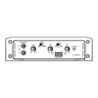
The REMOTE TURN ON CONNECTION is located on the barrier strip next to the power and ground connections. This connection turns the amplifier on and off with the rest of the system. A smaller gauge wire can be used to connect this to the radio's power antenna lead. If the system lacks turn-on leads, the remote terminal can be wired to an accessory lead that turns on with the car's ignition.
POWER/GROUND WIRING instructions emphasize that Cadence FXA series amplifiers come with built-in fuses, and users should never replace them with fuses of a larger value.
- It is suggested to construct a Red wiring harness with two additional fuses: one near the car battery for protection against short circuits to the car chassis, and a second closer to the amplifier for additional safety. This fused red power wire should be attached to the amplifier power terminal marked +12V.
- The wire harness should be made of red primary cable, at least 8 gauge for the FXA1000.2 and at least 4 gauge for larger models. It should terminate in a large ring terminal for connection directly to the positive terminal of the car battery, using a spade plug for attachment to the +12V terminal.
- A black wire of equal gauge should be used for the ground connection to a welded chassis member. Ensure no paint or insulator blocks a good ground connection. When installing multiple amplifiers, mount them in close proximity to share the same ground point. Attach the black ground wire to the amplifier screw terminal marked Ground.
- Cadence AMPKIT4 or AMPKIT8 installation kits are recommended for a good, reliable installation.
- The manual warns that melted power/ground terminals are often caused by bad ground connections, leading to heat buildup at the contact screw of the amplifier terminal. Users are advised to feel the power and ground wires near the amplifier connection after playing the amp for a while. If they feel hot, it indicates a bad or loose connection. If connections are secure but wires still feel hot, upgrading to a heavier gauge wire is recommended.
SETTING THE CONTROLS section explains how to configure the amplifier's audio settings.
- AUDIO PREAMP INPUT: Cadence FXA series amplifiers feature RCA preamp inputs. RCA cables should be run from the sound source to the amplifier inputs. High-quality shielded RCA patch cords are recommended to reduce electrical noise. RCA cables should be run on the opposite side of the vehicle from the power and ground leads.
- BUILT IN LOW PASS ELECTRONIC FILTER: All Cadence FXA series amplifiers feature 12dB per octave fully adjustable low-pass and high-pass electronic filters.
- For Low Pass subwoofer systems, set the FILTER switch to LOW PASS. The LPF or LOW PASS knob controls frequencies from 50Hz to 500Hz (depending on the model). A common mistake is setting the frequency too low, especially with vented subwoofer enclosures. For most installations, setting the frequency knob between 80 to 100Hz (the 12 o'clock position) is recommended.
- For component or coaxial speakers, set the FILTER switch to HIGH PASS. The HPF control knob adjusts high-pass frequencies between 120Hz and 3KHz. Tweeters should not be attached directly to the amplifier (even in high-pass mode) without a passive crossover for protection.
- SUBSONIC FILTERING: For subwoofer installations with passive LP crossover, the amplifier's FILTER switch can be set to HIGH PASS while the SUB SONIC knob is set to 30Hz. This acts as a SUBSONIC FILTER for signals below 30Hz, which is useful for vented enclosures where the port tuning frequency falls below the subwoofer tuning frequency, protecting against subwoofer unloading.
- GAIN (INPUT LEVEL CONTROL): To adjust the GAIN, turn the control fully counter-clockwise using a small flat-head screwdriver, being careful not to apply pressure. Adjust the radio volume to maximum, then turn the amplifier's level control clockwise until audible distortion occurs. Once distortion is heard, back down one notch. Having a second person assist with this setting is helpful.
- For multi-amp systems, set each amplifier's gain separately, starting with the bass amplifier and then matching the highs amplifier's level control.
- After setting the level controls, use any equalizer controls to adjust the system's tonal level for personal preference. Keep in mind that equalizing may require readjusting the amplifier's level controls.
- The manual clarifies that the level control is not a volume control but a device to match the source unit's output level to the amplifier's input level. The amplifier gain should not be set to maximum unless the input level requires it.
The MOUNTING section provides instructions for physically installing the amplifier.
- Choose a convenient mounting location with unobstructed airflow.
- Cadence FXA series amplifiers have four mounting tabs near the corners. Use the supplied screws and grommets to gently mount the amplifier.
- Users are warned not to overtighten the screws.
The manual then provides several WIRING DIAGRAMS for different amplifier configurations:
- 4 CHANNEL AMP WITH 2 CHANNEL INPUT: Illustrates how to use RCA Y adaptors to split the signal from a head unit with only one pair of Left and Right RCA outputs, directing them to Channels 1/2 and 3/4.
- 4 CHANNEL AMP WITH 4 CHANNEL INPUT: Shows how to connect a head unit with two pairs of RCA outputs (Front Left/Right to Channels 1/2, Rear Left/Right to Channels 3/4). It also explains how to configure a 4-channel amplifier into a 3-channel system using RCA Y adaptors to send the subwoofer preamp signal to channels 3 and 4, bridging them for the subwoofer, while preserving Left and Right balance.
- 4 CHANNEL AMP WITH 4 CHANNEL OUTPUT (FXA 2400.4): Details how to install any combination of speakers independently on all four channels, emphasizing not to load any single channel below 2 ohm stereo.
- 4 CHANNEL AMP BRIDGED TO 2 CHANNELS (FXA 2400.4): Explains how to bridge the four-channel amplifier, ensuring the final woofer impedance on each bridged channel is no lower than 4 ohms. The Crossover mode switch should be set to Low Pass, with the crossover frequency control initially set to 100Hz and then tuned.
- 4 CHANNEL AMPLIFIER IN 3 CHANNEL MODE (FXA 2400.4): Describes wiring Channels 1 and 2 to speakers (no lower than 2 ohm stereo) and bridging Channels 3 and 4 for a woofer (to Channel 3 positive and Channel 4 negative terminals). Channels 1 and 2's crossover mode switch should be set to High Pass, while Channels 3 and 4 should be set to Low Pass.
- 4 CHANNEL AMPLIFIER IN 3 CHANNEL MODE (FXA 2400.4) with Passive Crossover Values: Provides a table of component values for a 6dB passive crossover, including frequency, inductor, and capacitor values, for use with the 3-channel mode.
- 4 CHANNEL WITH DUAL MIXED MONO CONFIGURATION (FXA 2400.4): Explains a configuration where all crossover settings should be set to FULL RANGE. It also includes a table of component values for a 6dB passive crossover.
- 2 CHANNEL AMPLIFIER 2 OHM / 4 OHM STEREO (FXA 1000.2, FXA 1600.2): For this configuration, the crossover mode switch should be placed in full range.
- 2 CHANNEL AMPLIFIER 4 OHM BRIDGED (FXA 1000.2, FXA 1600.2): For this configuration, the crossover mode switch should be placed in low pass position.
- 5 CHANNEL AMP WITH 5 CHANNEL OUTPUT (FXA 5000.5): Details installing any combination of speakers independently on all five channels, ensuring no single channel is loaded below 2 ohm stereo. A note clarifies that the Dash Board Bass Remote Control feature on the FXA 5000.5 functions as a bass equalizer, not a bass volume control.
- CLASS A/B MONO BLOCK 2 OHM AMPLIFIER (FXA 1500.1): This model is a 2 ohm Class A/B mono block amplifier. Regardless of the number of woofers, the final impedance should not fall below 2 ohms. The manual refers to subsequent pages for various speaker impedance configurations. A note clarifies that the Dash Board Bass Remote Control feature on the FXA 1500.1 functions as a bass equalizer, not a bass volume control.
- CLASS -D MONO BLOCK 1 OHM AMPLIFIER (FXA 2500.1D): This model is a 1 ohm Class D mono block amplifier. The final impedance should not fall below 1 ohm, regardless of the number of woofers. The manual refers to subsequent pages for various speaker impedance configurations. A note clarifies that the Dash Board Bass Remote Control feature on the FXA 2500.1D functions as a bass equalizer, not a bass volume control.
The manual also includes a SPEAKER WIRING CHART with diagrams for various speaker configurations:
- 4 X DUAL VC 8 OHM SPEAKERS WITH SERIES VOICE COILS, ALL IN PARALLEL: Shows how to wire four dual voice coil 8 ohm speakers in series voice coils, all in parallel, resulting in a 2 ohm load to the amplifier.
- SERIES: SINGLE VOICE COIL SPEAKERS: Illustrates wiring single voice coil speakers in series, showing 8 ohm, 4 ohm, and 2 ohm speakers connected to achieve 4 ohm, 2 ohm, and 1+1 ohm loads respectively.
- PARALLEL: SINGLE VOICE COIL SPEAKERS: Illustrates wiring single voice coil speakers in parallel, showing 2 ohm speakers connected to achieve a 4+4 ohm load.
- 2 X DUAL VC 2 OHM SPEAKERS WITH SERIES VOICE COILS, ALL IN PARALLEL: Shows how to wire two dual voice coil 2 ohm speakers with series voice coils, all in parallel, resulting in a 2+2 ohm load.
- A general note advises that the minimum impedance load for a single Cadence FXA series amplifier is 2 ohm stereo and 4 ohm mono bridged. Lower impedance loads can cause overheating and damage to the amplifiers.
- Users are warned not to mix different impedance speakers in series and/or parallel combinations, as this can lead to unequal power sharing and acoustic outputs.
Finally, the manual concludes with a disclaimer: "Due to constant product improvements, these specifications are subject to change without notice. Though we tried our best to insure that this manual is free and clear of errors please don't hold us responsible for printing errors." It also includes a copyright notice for Cadence Acoustics LTD.