Do you have a question about the Cadence XENITH series and is the answer not in the manual?
Should you need technical assistance during or after your installation please call our technical-line between 9:30 am and 5:00 PM EST.
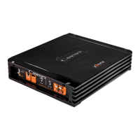
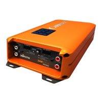
Use of this amplifier at extreme high volumes may cause hearing loss and impair driving awareness. Secure amplifier tightly.
Sophisticated IC controlled protection circuitry monitors temperature and voltages. Anti-thump, mute, and delay circuit included.
Features narrow "Q" shelving equalization circuit for bass boost and a robust PCB design.
Rated and regulated to 13.8 volts; maximum input voltage is 14.4 volts.
Includes Thermal, Speaker Short Circuit, Input Overload, and DC Offset Protection.
Disconnect battery, secure amplifier, proper power/ground wiring, and fuse usage are critical.
Use appropriate gauge primary cable for power and ground connections for reliable installation.
Connect remote turn-on wire and run RCA cables for audio signal input.
Features 12dB/octave fully adjustable low-pass and high-pass electronic crossovers.
Approximate crossover points for low-pass filters should be set around 100 Hz for subwoofers.
Adjust INPUT GAIN to match source unit output level without audible distortion.
Input Gain matches source to amplifier; it is not a substitute for system volume control.
Mount amplifier in a location with unobstructed airflow for efficient heat dissipation.
Chart provides guidance on selecting correct wire gauge based on total amperage and wire run distance.
Shows proper connection of power, ground, remote, and speaker for mono block amplifiers.
Wiring configurations for stereo speakers or subwoofers using 2-ohm or 4-ohm loads.
Wiring for component kits with passive crossovers.
Connecting a 4-ohm subwoofer in bridged mode.
Wiring for two bridged 4-ohm subwoofers.
Connections for component kits or coaxial speakers on channels 1-2 and 3-4.
Diagram for a three-channel system using component kits or coaxial speakers.
Diagram for wiring a single 4-ohm subwoofer in bridged mode.
Connect stereo amplifier to head unit, then mono amp to stereo amp's pre-out for multi-amp setups.
Diagrams illustrate series/parallel wiring for dual voice coil speakers to achieve desired impedance.
Using loads lower than specified (2-ohm stereo, 4-ohm mono bridged) can cause overheating and damage.
| Series | XENITH |
|---|---|
| Signal-to-Noise Ratio | >90dB |
| Input Sensitivity | 200mV - 6V |
| Bass Boost | 0dB - 12dB @ 45Hz |
| Dimensions | Varies by model |