Installazione
Installation
Einbau
Installation
Instalación
Instalação
Installatie
Per una corretta installazione occorre attenersi alle seguenti istruzioni:
- per la selezione della lamella è necessario individuare il diametro della
tubazione sulla quale l’apparecchio va installato;
- sull’apparecchio è premontata la lamella da 1”;
- per diametri uguali o superiori a 1 1/4” (DN 32) occorre rimuovere la
lamella premontata da 1” e montare la lamella lunga tagliandola alla misura
corrispondente al diametro desiderato;
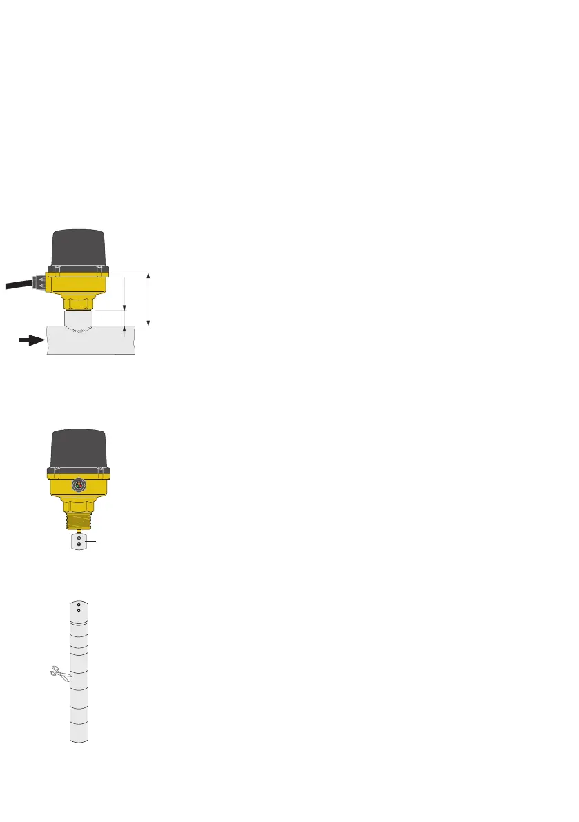
- installare il flussostato sulla tubazione attenendosi al senso del flusso
indicato dalla freccia stampigliata sul coperchio e
sulla parte esterna
del
corpo, ed in modo tale che la distanza tra la superficie superiore della
tubazione ed il punto di giunzione tra corpo e coperchio del flussostato
sia di 80 mm;
- il collegamento alla tubazione può essere effettuato saldando
direttamente un manicotto filettato, anche per il diametro di 1” in quanto
le lamelle sono studiate per essere contenute in dimensioni ridotte.
È tuttavia opportuno controllare che la saldatura sia esente da bave nella
sua parte interna in modo che la lamella possa ruotare liberamente nel
manicotto;
- l’apparecchio deve essere installato possibilmente con asta di comando
in
posizione verticale per evitare depositi di impurità che causerebbero il non
corretto funzionamento.
To fit the switch correctly follow these instructions:
- when selecting the blade, identify the diameter of the pipe to which the
appliance will be fitted;
- the appliance comes pre-fitted with the 1” blade;
- for diameters of 1 1/4” (DN 32) and above, the pre-fitted blade should be
removed and the long blade fitted, cutting it to the correct corresponding
size for the desired diameter;
- fit the flow switch to the pipe, carefully observing the direction of flow
indicated by the arrows stamped on the cover and on the switch
mounting
plate. When fitted, the distance between the upper surface of the
pipe and
upper surface of the switch mountuing plate should be 80 mm;
- the tee connection in the pipe can be formed by the direct welding of a
threaded socket;
- this also applies to a 1” diameter pipe, as the blades are designed to be
contained in these smaller dimensions. It is however advisable to check
that the weld is free from burrs on the inside so that the blade can move
freely in the tee connection;
- whenever possible the appliance should be installed
with control stem
in
the vertical position
to avoid deposits of impurities which may cause it to
function incorrectly
.
Für einen korrekten Einbau muß folgendes beachtet werden:
- Bei der Wahl des Paddels muss der Durchmesser der Leitung ermittelt
werden, auf der das Gerät installiert wird;
- An der Armatur ist ein 1”-Paddel vormontiert;
- Bei Durchmessern von 1 1/4” (DN 32) oder größer muss das vormontierte
1”-Paddel entfernt und das lange Paddel montiert werden, welches auf den
gewünschten Durchmesser zugeschnitten werden muss.
- Den Strömungswächter unter Beachtung der Fließrichtung (siehe
Pfeil auf Deckel und Körper) so in die Rohrleitung einbauen, daß
die Einbauhöhe,
gemessen von der Oberfläche des Rohrs bis zum
Verbindungspunkt von Deckel und Körper
des Strömungswächters, 80 mm
beträgt.
- Der Einbau ins Rohr erfolgt durch Anschweißen einer Muffe mit einem
Innengewinde von G 1”. Es wird empfohlen, zu kontrollieren, daß im
Inneren keine Schweißgrate zurückgeblieben sind, damit sich das Paddel
beim Einschrauben frei in der Muffe drehen kann.
- Das Gerät muss mit dem Paddel nach unten in vertikaler Lage eingebaut
werden, um Ablagerungen auf dem Paddel vorzubeugen, die das korrekte
Funktionieren des Gerät beeinträchtigen würden.
80 mm
20 mm
1"
1
1
2"
2
8"-DN200
6"-DN150
5"-DN125
4"-DN100
3"-DN 80
DN175
1"
3"-DN 80
4"-DN 100
5"-DN 125
6"-DN 150
8"-DN 200
7"-DN 175
2 1/2"
1 1/2"
1 1/4"
2"
3
 Loading...