7
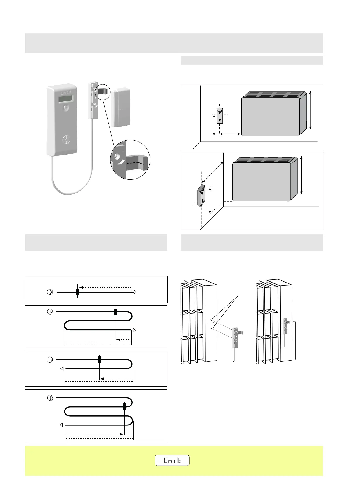
In order to ensure measurement according to the regulations, the heat cost
allocator must be positioned at a distance not less than 10 cm from the
heating body and at a height equal to half the height of the heating body.
10 cm
10 cm
50% H
50% H
H
H
50% H
10 cm
H
50% H
10 cm
H
The sensor must be positioned at 75% (±1 cm) of the coil
development (25% from the inlet, 75% from the outlet).
75% (±1 cm)
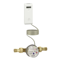
The remote sensor is to be fitted on the return chamber at 50% of the
height.
N.B. The remote probe must be installed in such a way that any
attempt to disconnect the probe will leave a trace.
Therefore, use the tamper-proof label provided on the outer probe
cover.
75% (±1 cm)
75% (±1 cm)
75% (±1 cm)
During installation, make sure that the centre-line of the part shown
in Figure 1 is positioned exactly at 75% (±1 cm) of the development
of the coil or at 50% (±1 cm) of the height in the case of a single-
block convector.
2. INSTALLATION AND MAPPING (to be carried out by the installer)
MONITOR 2.0 E (with remote probe)
Determination of the extended probe sensor position
Single-fin or coil convector
FASTENING WITH SCREWS OR CLAMPS
WELD FASTENING
Determination of the remote probe sensor position
Single-block convector
Heat cost allocator position with convector
10 cm
10 cm
50% H
50% H
H
H
50% H
10 cm
H
50% H
10 cm
H
N.B. When installation is complete, the heat cost allocator is automatically activated after about 90 seconds.
The following appears on the display:
You can now proceed with parameterisation of the heat cost allocator (see page 17).
①
N.B. If using a remote probe with a radiator, the centre-line of the
probe positioning indicator must be positioned (instead of the thermal
coupling plate) according to the instructions given on page 6.
copper pin
positioning
points
50% H
(±1 cm)
 Loading...