® ET2000e IRRIGATION CONTROLLER INSTALLATION
making
since 1986
ater work
Electrical Hookup
120 VAC Power Connections and Unit Grounding
Perform all 120 VAC electrical and grounding
hookup per local and national electric code.
• Connect the 120 VAC power line to the input
wires of the transformer. Connect one side
to the black wire and the other to the white
wire.
• Enclose the 120 VAC power line in conduit
approved for grounding and connect
securely to the transformer nipple. The
conduit is to be grounded and will serve as
the controller ground.
Station Wire Connections
CAUTION:
NEVER
touch station wires and field wires together
while the station is activated (e.g. for identifying
valves before wiring a controller). This could result
in damage to the irrigation controller.
• Use the attached Station Wire Color Code
chart to locate the correct color wire in the
wiring harness and attach it to the station
wire using wire nuts or terminal strips.
• Repeat this procedure for all stations.
• Connect both white wires on the black
connector to field common and #6 ground
wire as shown in the Grounding Instructions
included with the controller.
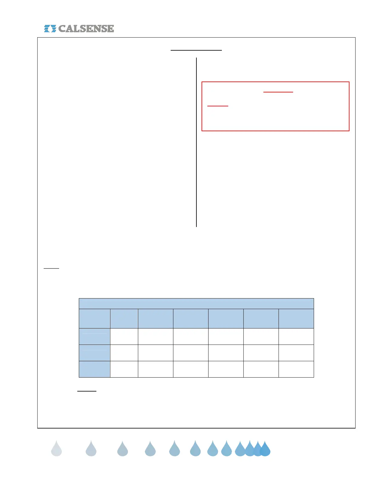
Loading Examples
The following chart provides loading examples with remote control valves and relays.
Note:
The total load must never exceed 1.5 amps. Also note not all solenoids draw .3 amps.
LOADING EXAMPLE CHART
STATION STATION STATION
MASTER
VALVE
PUMP TOTAL
Case 1
S S R 0.8A
Case 2
S S S R 1.1A
Case 3
S S S S R 1.5A
Notes: S stands for a 0.3 A solenoid.
R stands for a 0.2A relay coil.
Any single output may be loaded to 1.5A.
The total load must never exceed 1.5A.
CHANGE 1 12 March 2007
 Loading...