ET2000e IRRIGATION CONTROLLER INSTALLATION
®
making
since 1986
ater work
Remote Control (Orange wire)
When connecting a Remote control interface cable,
use the same station wires and common as
connected to the field wires. The 24 volt wire on the
Radio Remote interface cable should be connected
to the orange wire on the black harness.
Flow Meter (Red and Black wires)
If a flow meter is used, it is to be connected to the
red and black wires on the black harness. Make sure
to connect the red wire from the controller to the red
wire on the flow meter, and the black wire from the
controller to the black wire on the flow meter. The
flow meter connections must be watertight or the
flow meter will not operate properly. NEVER
use
buried splices. DO NOT connect flow meter to 24
VAC or 12 VAC outputs.
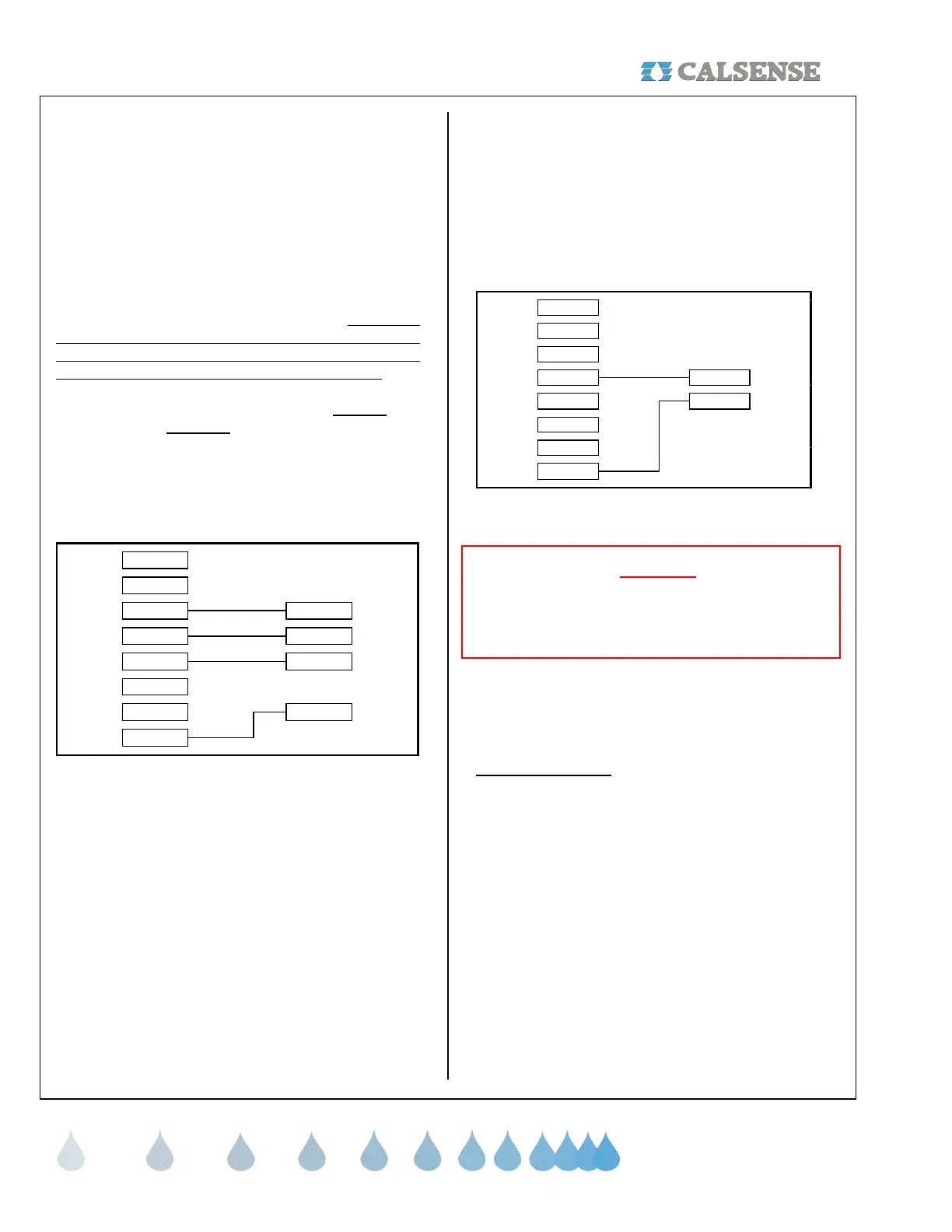
Rain Cups (Orange, White, Yellow wires)
Rain Cups are normally used to break the common
wire between the controller and the valves. DO NOT
install the rain cup in this manner with Calsense
irrigation controllers because it will disable some of
the controllers features. Installation should be done
according to the following diagram. Calsense
recommends either the Mini-clik or the WCS 4 wire
Rain Guard/ RG DCC which have mechanical
switches.
MINI-CLICK
YELLOW
CALSENSE CONTROLLER
BLACK WIRING HARNESS
BLUE
(SILVER WIRE)
BLUE
(COPPER WIRE)
WHITE
WHITE
BLUE
GREEN
RED
BLACK
ORANGE
Mini-clik wiring diagram
BLUE
GREEN
RED
BLACK
ORANGE
WCS RAINGUARD MODEL RG DCC
YELLOW
CALSENSE CONTROLLER
BLACK WIRING HARNESS
RED
WHITE
BLUE
GREEN
(LOOSE)
WHITE
WHITE
WCS Rainguard model RG DCC wiring diagram
Installing the irrigation controller in the cabinet
(2 Orange, 2 Blue wires)
• First plug in the color coded connectors into
the printed circuit board. The color of each
connector is printed on the board, beneath
it’s plug. The size of the controller
determines how many color coded
connectors there will be. After all color
coded connectors are in place, plug in the
transformer power plug (The small white
connector with two (2) orange and two (2)
blue wires.
CAUTION:
When installing the connectors please note that
they only go on one way. Do not attempt to force
them on upside down.
• Next put the irrigation controller in the
cabinet and secure it with the four (4)
mounting screws.
System Check out
Before operating the stations from the irrigation
controller, it is suggested that all the wires be
checked for proper connections. If station flow rates
and moisture sensor measurements are to be
checked then use either the TEST or MANUAL key.
Refer to the instruction sheet located inside the door
of the controller to operate MANUAL or TEST
modes.
Moisture Sensor Installation
Please cal the factory at 1-(800)-572-8608 for
assistance in sensor placement and operation.
CHANGE 1 12 March 2007
 Loading...