® ET2000e IRRIGATION CONTROLLER INSTALLATION
making
since 1986
ater work
ADDITIONAL IRRIGATION CONTROLLER OPTIONS
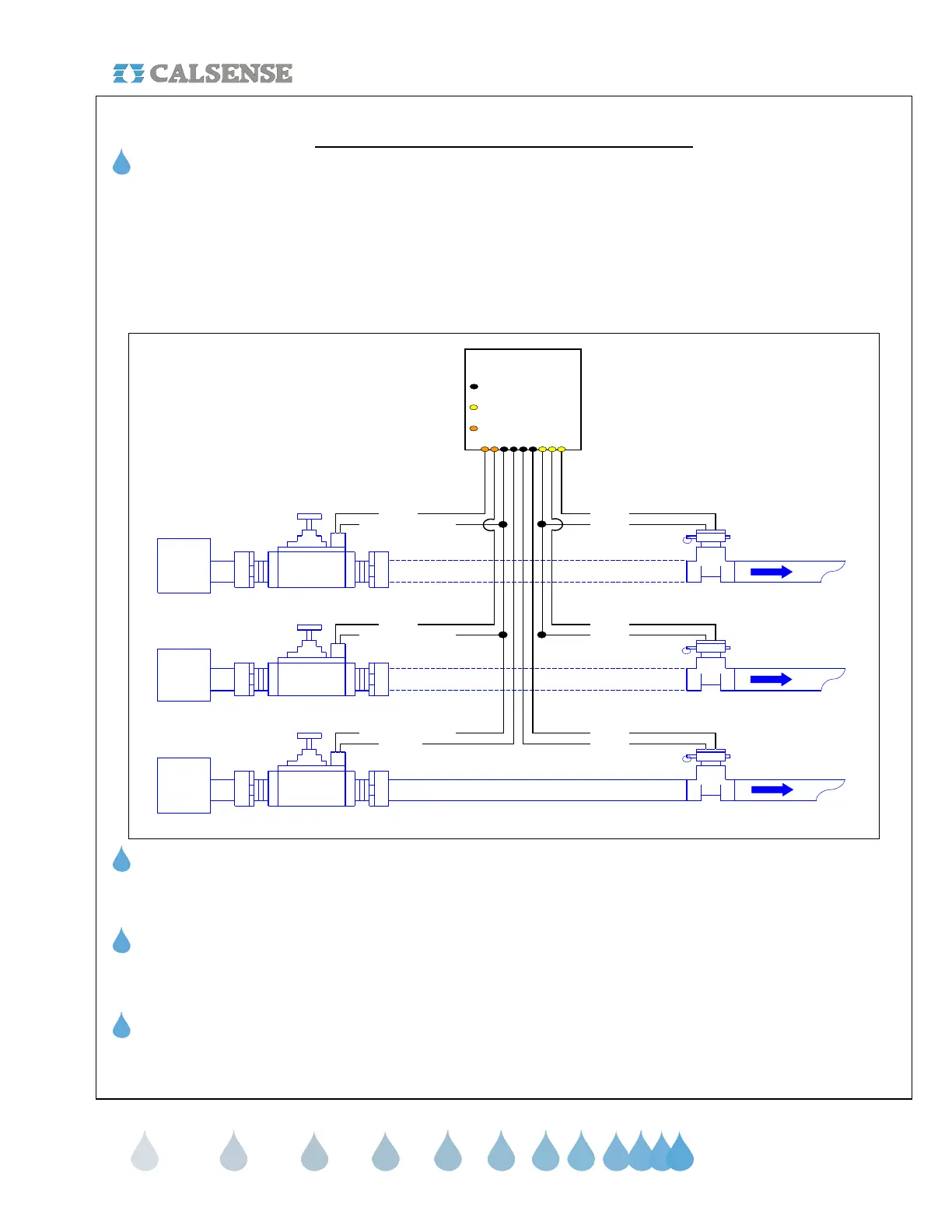
Multiple Flow Meter Interface (-F option)
Calsense ET2000e Irrigation Controllers can receive up to three (3) separate flow inputs and (3) separate Master
Valve inputs with projects consisting of more than one water source for irrigation landscape. However the
irrigation controller must be specified with the –F option. The first flow meter is wired to the irrigation controller as
described in the Flow Meter installation Instructions. The second and third Flow Meters are wired to the irrigation
controller using the additional (-F) Flow Meter cable. The second and third Master Valves are wired to the
irrigation controller using the Orange harness black and red wires respectfully. Use the following diagram:
Note: Wire harnesses are color
coded into groups. Station
Harnesses, Options, etc.
MAINLINE
RED ORANGE
BLACKWHITE (FIELD COMMON)
Calsense Controller
ET2000e ONLY
Wires found in controller Black
harness
Wires found in controller
Orange harness
Calsense New
(-F) Option
Wiring Diagram
Wires found in controller
communications
/ options harness
P.O.C 1
Normally
OPEN / CLOSED
Master Valve
Water
Main
WHITE (FIELD COMMON)
WHITE (FIELD COMMON)
Flow Meter 1
Water
Main
P.O.C 3
Normally
OPEN / CLOSED
Master Valve
Water
Main
P.O.C 2
Normally
OPEN / CLOSED
Master Valve
MAINLINE
MAINLINE MAINLINE
Flow Meter 3
RED
BLACKBLUE
RED
BLACK
MAINLINE
Flow Meter 2
BLACK
ET Gage Interface (-G option)
Refer to the ET Gage Installation Instructions provided with every ET Gage.
Rain Bucket Interface (-RB option)
Refer to the Rain Bucket Installation Instructions provided with every Rain Bucket.
Wind Gage Interface (-WG option)
Refer to the Wind Gage Installation Instructions provided with every Wind Gage.
CHANGE 1 12 March 2007
 Loading...