® ET2000e IRRIGATION CONTROLLER INSTALLATION
making
since 1986
ater work
CENTRAL COMMUNICATION
Non-Hardwired- -to Hardwired Communication (-M-LR, -M-CR, -M-SR, -M-EN, -M-WEN, -M-GR, M-FOM,
to a - M option)
Several irrigation controllers can share one Communications device. The irrigation controller which has the
communications device is designated with a –M plus the two letter communications option. The Communications
device is powered by the controller panel. All other irrigation controllers which are to be linked to the
Communications irrigation controllers are specified as - M’s.
The Communications irrigation controller comes with a coaxial antenna cable. This cable is simply screwed into
the dome antenna mounted on top of the enclosure or irrigation controller cabinet (see mounting instructions
included with antenna).
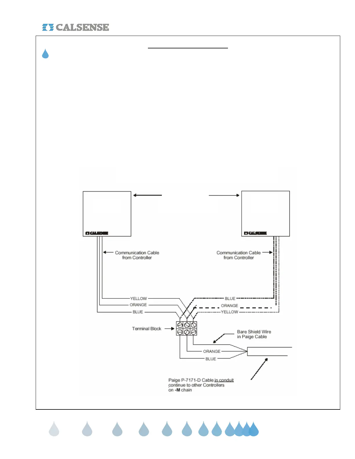
Paige P-7171-D cable is used to link the Communications irrigation controller(s) to the one - M. The maximum
number of - M irrigation controllers linked in a chain is 31. The maximum length of cable is 5,000 feet. Follow the
diagram below for proper wiring of the Paige cable to the irrigation controller.
-M-xx
-M
Calsense Model
COMMUNICATIONS CABLE WIRING DIAGRAM
CHANGE 1 12 March 2007
 Loading...