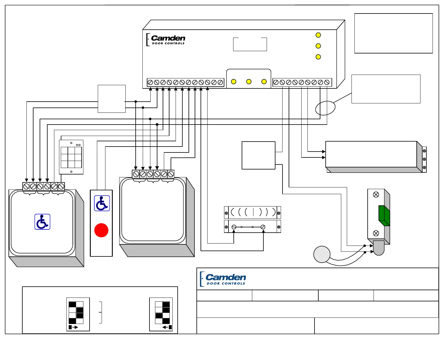
Inside
Wall Switch
(always Unlocks
& opens door)
FILENAME:
WC-13-8 wiring diagram.vsd
DRAWING No: DRG-CX-WC-13-8
WC-13 Washroom Package Wiring Diagram (normally locked)
SCALE: NONE DRAWN BY: DGW REVISED:DATE: 07/22/14
Magnetic
Contact
Switch
12 - 24 V
AC/DC
Power
Outside
Inside
Push to Lock
CM-45/8GRESE1
(or similar)
Wall Switch
CM-45/4GRESE1
(or similar)
Fail-Secure
Electric Strike
Shown
MOV
Wire MOV
(supplied)
directly to strike
(If Fail-Safe lock is
used, wire to
Terminals 1 & 2)
N.C.
Contacts closed
when Door
is closed
12 / 24 VDC
Power
For Strike
For Normally Unlocked Door, see over...
PUSH
TO
LOCK
12/24V
Power
Remote
N.O.
Relay
Output
LED 1
CX-33
LED 2
LED 3
DISPLAY
Relay 1 Relay 2 Relay 3
N/C
N/O
COM
N/C
N/O
COM
N/C
N/O
COM
POWER
12/24V
AC/DC
DRY 1
DRY 2
DRY 3
DRY 4
+ WET
INPUT
INPUT
INPUT
INPUT
- INPUT
MENU UP DOWN
0.0.8
Door
Operator
PUSH
TO
OPEN
PUSH
TO OPEN
12/24V
Power
Remote
N.O.
Relay
Output
NOTE: This Drawing should be
used in addion to each products
respecve Installaon Manual.
(not in place of)
1 2 3
4 5 6
7 8 9
Keypad Keyswitch
Prox Reader
or similar
+
-
The following items are required, but NOT included:
- Door Operator
- Electric Strike
- Inside Acvate wall switch
- 12 / 24V power supply
The following are part of the WC-13 package:
- CX-33 Relay
- CX-MDC Door Contacts
- CM-45/4GRESE1 Illuminated Push plate switch
PUSH TO OPEN,
,
with signage
- CM45/8GRESE1 Illuminated Push plate switch
PUSH TO LOCK with signage
Important:
Ensure wiring polarity is
consistent from Relay 3 to each
Aura´s Remote Input terminals.
CAMDEN DOOR CONTROLS
5502 Timberlea Blvd.
Mississauga, Ontario
L4W 2T7
Red
IDL
G/B
Red
ACT
G/B
4
3
LOC/REM
RELAY
2
1
Enable
SPEAKER
ON
1
2
3
4
Color Select
Aura
Dip Switch
Settings
ON
 Loading...
