FILENAME: TX-9 Installation Drwg.vsd
DRAWING No: TX-9-Installation
TX-9 Typical Installation Examples
SCALE: NONE
DRAWN BY: DGW
REVISED: 16/09/15
DATE: 03/24/10
5502 Timberlea Blvd
Mississauga, Ontario
L4W 2T7
+
-
+
-
+
-
+
-
+
-
+
-
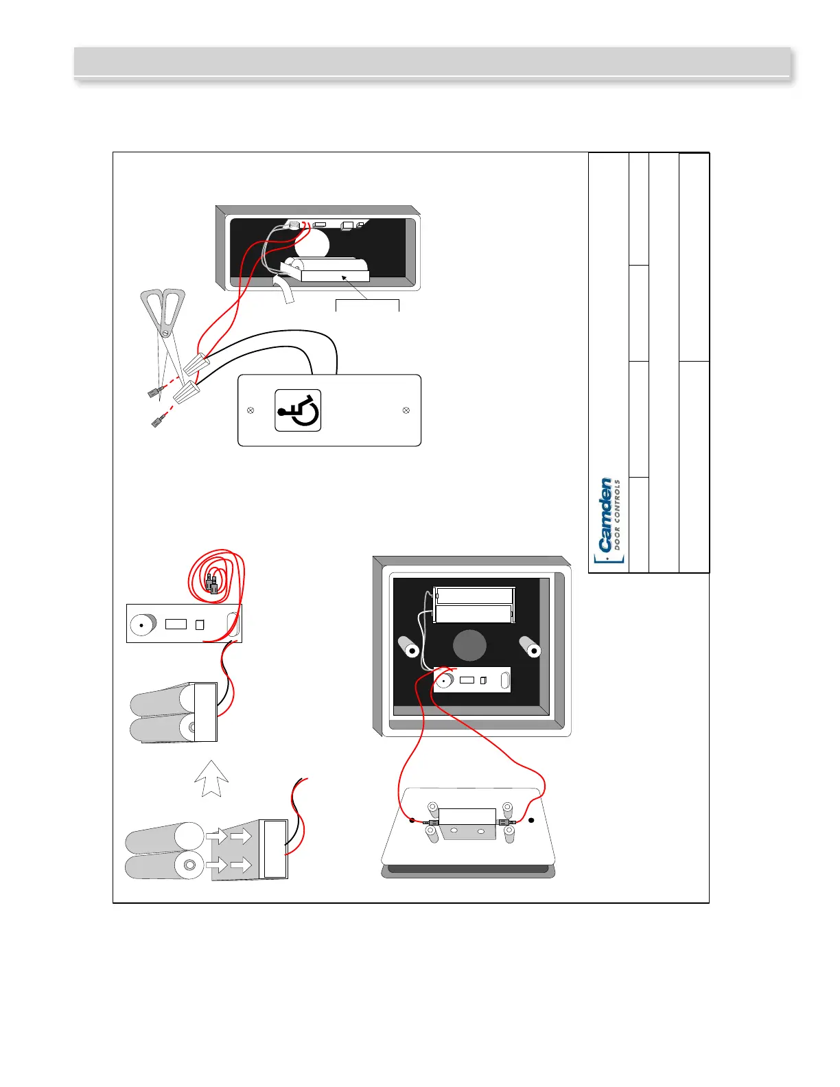
STEP 1
STEP 2a
STEP 2b
OR
Insert two fresh AAA batteries into
battery holder, taking care to match the
positive and negative terminal markings
on case.
USING WITH OUR CM-45 SWITCH & CM-43 BOX
Peel off the release paper on the back of the transmitter
and batter holder.
Position on back of the enclosure ensuring clearance for
the switch (as shown above).
Connect the two red leads to the N.O. and Common
terminals of the switch and mount switch to enclosure
.
Test for proper operation.
USING WITH OUR CM-25 SWITCH & CM-23d BOX
Peel off the release paper on the back of the transmitter and
battery holder.
Position on each side of the enclosure ensuring battery
holder is tight to the bottom of box (as shown above).
Cut off the two ¼" Female connectors, and strip wires.
Connect to the two leads from switch using small twist-on
MARR connectors.
Install switch to box, and test for proper operat
ion.
Part # 40-82B120
+
+
AAA
AAA
COM
N.O.
AAA
AAA
PUSH
TO
OPEN
Affix battery
holder to side of
box as close to
bottom as
possible
Camden Door Controls
 Loading...