EasyManua.ls Logo

CAMET CAA-500 User Manual

CAMET CAA-500
4 pages
To Next Page IconTo Next Page
Page #1 background imageLoading...
Page #1 background image
Precautions for operation
l The CAA-500 has its Impedance Bridge just inside the Output Connector. Never apply power from an
external transmitter to the CAA-500. Failure to follow this could cause damage to this product.
l The external DC supply voltage must be between 8 to 16 Volts, and the current supplied must be at
least 250mA. Never apply DC voltages greater than 16 Volts, nor AC voltage of any kind. Our warranty
does not cover damage caused by the use of an improper power source.
l When using AA batteries, the decimal point on the Frequency Counter will blink when the weak
batteries are weak. Change batteries as soon as it starts blinking, and change all batteries to improve
the battery shelf life.
Remove the batteries when not in use for extended periods of time
(*some rechargeable batteries, which have 1.2V rated voltage, are not appropriate for long-time continuous
operation).
Instruction Manua
l
Thank you for your purchasing our product. This product is made under the
most stringent quality controls. Should there be any breakage in transit,
please do not hesitate to contact the shop from which you purchased this
product for instructions on resolution of the problem.
For your safety, please read this manual carefully for instructions on proper
handling and operation before using.
Features
l Built-in broadband high-stability transmitter for easy measurement of resonant frequency,
SWR, and impedance.
l Cross-needle meter display provides SWR and Impedance information simultaneously.
l 12 hours of continuous use with AA alkaline batteries.
l Hand strap attachment for safety.
Question and Answer IconNeed help?

Do you have a question about the CAMET CAA-500 and is the answer not in the manual?

CAMET CAA-500 Specifications

General IconGeneral
BrandCAMET
ModelCAA-500
CategoryMeasuring Instruments
LanguageEnglish

Summary

Appearance & Components

Display Meter

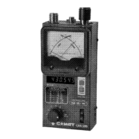
The cross meter display indicates SWR and impedance simultaneously.

Frequency Counter

This 6-digit LED display indicates the frequency to which the CAA-500 is currently set.

Freq Range Selector

6 frequency ranges are provided, yielding coverage of 1.8-500 MHz.

Battery Case

The battery case accepts six "AA" alkaline batteries to power the CAA-500.

External Power Supply

An external DC power supply (8-16V, 250 mA minimum) may be connected here.

FREQ Knob

This knob adjusts the operating frequency of the CAA-500, in conjunction with the Freq Range Selector.

POWER Switch

This is the main Power On/Off switch for the CAA-500.

Gate Time Switch

This switch selects between display resolutions of 1 kHz (FAST) and 100 Hz (SLOW).

Output Connector

Two output connectors are provided; use "M" for "A"-"F" ranges, "N" for "High Range".

Hand Strap Attachment point

The Hand Strap may be attached here; any suitably-strong strap of at least 1 mm diameter may be utilized.

How to use

Preparation

Operation check before using CAA-500: connect dummy load, check display, verify SWR/impedance.

SWR Measurement

Connect antenna, select frequency range, adjust knob, read SWR on scale.

Impedance Measurement

Connect antenna, select frequency range, adjust knob, read impedance on OHMS scale.

Antenna Resonance Frequency Measurement

Find resonant frequency by selecting range, adjusting knob, and noting lowest SWR.

Precautions During Operation

After-Sales Service