15Instruction manual Extraction MotorsPlease keep this instruction manual for future reference
INSTALLATION:
This product is to be installed by a qualified technician. Using the appropriate drilling jig
(Fig.14) drill all the holes marked on it into the external wall, paying attention not to damage
water pipes or power lines.
The holes on the wall are to be drilled with an 8mm bit. Insert, step by step, the following parts
in the holes drilled:
› The corresponding plastic dowels supplied (Fig.14).
› Two ducting channels (not supplied) in the hole of 200mm.
› Plastic pipe of 40mm diameter (not supplied).
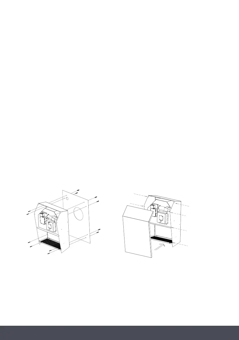
Before leaning the appliance against the wall, remove the stainless-steel cover using the 8
perimetrical screws (Fig.15), then insert the supply cord in the plastic ducting.
Fix the appliance without the stainless-steel external body, which was previously removed from
the motor block, by matching the holes of the motor block with the holes on the wall.
Tighten with the screws supplied.
> The corresponding plastic dowels supplied (Fig.14).
> Two ducting channels (not supplied) in the hole of 200mm.
> Plastic pipe of 40mm diameter (not supplied).
Before leaning the appliance against the wall, remove the
stainless-steel cover using the 8 perimetrical screws (Fig.15),
then insert the supply cord in the plastic ducting.
Fix the appliance without the stainless-steel external body,
which was previously removed from the motor block, by
matching the holes of the motor block with the holes on
the wall.
Tighten with the screws supplied.
FIG.13
FIG.14
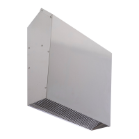
DDMEXT40
This product is designed to efficiently exhaust fumes
and odours. It must be installed on the outside wall of
the house and connected to the cooker-hood in the
kitchen (Fig.13).
INSTALLATION:
This product is to be installed by a qualified technician. Using
the appropriate drilling jig (Fig.14) drill all the holes marked on
it into the external wall, by paying attention not to damage
water pipes or power lines.
The holes on the wall are to be drilled with an 8mm bit. Insert,
step by step, the following parts in the holes drilled:
FIG.15
 Loading...