Do you have a question about the Carbine PLUS-4500 and is the answer not in the manual?
Locate and secure the alarm control module within the passenger compartment, avoiding engine bay or trunk.
Secure the siren in the engine compartment with a direct sound path to the ground for maximum output.
Install pin switch and bracket for hood/trunk, ensuring contact and weather protection.
Mount the switch in a hidden, accessible location for driver access, drilling a 1/4" hole.
Install the LED indicator by drilling a 5/16" hole and feeding wires to the control module.
The gray wire is designated for no connection in the main harness.
The blue wire with a white stripe is designated for no connection.
Connect the brown wire to the siren's positive wire and ground the siren's remaining wire.
The blue wire serves as a grounding trigger input for optional sensors.
Connect the green wire to the common wire of the door jamb switch for negative switched circuits.
Connect the violet wire to the common wire of the door jamb switch for positive switched circuits.
Provides a 1-second pulsed ground output when channel #2 is activated.
Connect the red/white wire to the parking light wire from the headlight switch.
Connect the pink wire to determine parking light relay output polarity.
A low current grounded output for activating interior lighting, requiring an additional relay.
This socket is specifically for use with the ALA-RPT Relay Pack.
Connect the red wire to the positive battery post or constant power wire for optimal operation.
Connect the black wire directly to the vehicle frame for a secure ground connection.
Connect the yellow wire to a +12 volt wire switched by the ignition key.
Configure switch #1 for .8 or 3.5 second door lock output timing based on vehicle type.
Set switch #2 to control whether door locks engage upon automatic arming.
Use switch #3 to enable or disable the current sensing trigger circuit.
Details wiring for 3-wire ground trigger door lock systems.
Wiring diagram for positive trigger door lock systems using a 3-wire setup.
Wiring for 5-wire ground at rest door locking systems with relay packs.
Wiring diagram for Mercedes door lock activation using relay packs.
Wiring for newly installed power door lock motors with relay packs.
Wiring for vehicles using a single wire for lock/unlock, with resistor fuse instructions.
Wiring for starter disable function using the ALA-RPS relay pack.
Wiring for starter/engine disable using the ALA-RPS2 relay pack.
Wiring diagram for connecting the alarm to the vehicle's parking lights.
Diagram showing the valet/override switch connection.
Wiring details for the dual zone electronic sensor plug.
Instructions for connecting the alarm status LED indicator.
Wiring for dome light supervision using the ALA-RPT relay pack.
Wiring for dome light supervision using a 30 Amp relay.
Wiring for trunk activation using the ALA-RPT relay pack.
Wiring for trunk activation using a 30 Amp relay.
Ensure the Valet/Override Switch is in the "Off" position before starting.
Plug in the Power Harness; siren and parking lights indicate readiness.
Turn the vehicle's ignition key to the ON position.
Switch the Valet Switch from Off to On, then back to Off once.
Switch the Valet Switch On then Off 2 times to enter programming mode.
Push the lock button on the transmitter; LED flashes, siren chirps to confirm learning.
Turn off the ignition; siren chirps confirm exit from programming mode.
Ensure the Valet/Override Switch is in the "Off" position before starting.
Press the Unlock Button to disarm the system; LED and siren indicate status.
Turn the vehicle's ignition key to the ON position.
Switch the Valet Switch On then Off 6 times to enter "Remote Feature Programming" mode.
Table detailing transmitter buttons and confirmation beep counts for changing functions.
Turn Off the Ignition to exit programming mode; siren chirps confirm.
Procedures for testing the basic functions of the alarm system.
Test procedure for the remote panic feature, including its automatic shut-off circuit.
Test procedure for automatic arming, requiring connected door jamb pins.
Procedure to test overriding the system and entering valet mode.
Procedure to test entering valet mode when the system is disarmed.
Procedure to test exiting valet mode and returning to normal security activation.
Test procedure for the starter disable feature if installed.
Explanation of the meaning of different LED flash patterns and states.
Explanation of the meaning of different parking light flash patterns.
Explanation of the meaning of different siren chirp patterns.
Testing procedure for power door lock and unlock functions.
Test procedure for the RF tamper re-arm feature.
Explanation of the re-arm timer and re-lock function after triggering.
Explanation of ignition controlled locking and unlocking behavior.
Procedure to test the channel #2 output function.
Test procedure for the dual zone sensor pre-warning indicator.
Details the system's power requirements.
Lists the types of trigger inputs supported by the system.
Specifies the current draw of the system when armed or disarmed.
Lists the various programmable timers within the system.
Details the maximum capacity for output wires.
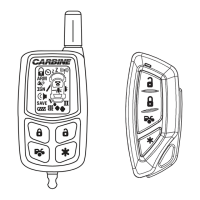
Provides specifications for transmitters and receiver channels.
Diagram showing the back view of the PLUS-4500 controller housing.
Illustrates the connections for the main wire harness.
Illustrates the connections for the power harness.