GB
MECHANICAL STOPS ADJUSTMENT (fig. C)
Models BLADE feature an internal system for mechanical stroke limitation composed of adjustable and independent stops
(parts 11 and 14 in fig. A), one for the opening stroke and one for the closing stroke.
Using these internal stops can be convenient when there are no stroke end stops or when there is no other way to limit the
stroke of the gate leaf. Where permitted by the installation it is anyway advisable to use or install gate leaf limit stops.
The adjustment is extremely simple:
- remove the screws (part 6 in fig. A) and remove the cover (part 4 in fig. A).
- move the leaf towards the actuator maximum stroke limit and fully tighten the screws of the mechanical stops
- perform opening and closing cycles to check the stops are correctly positioned and then refit the actuator cover.
GB
21
22
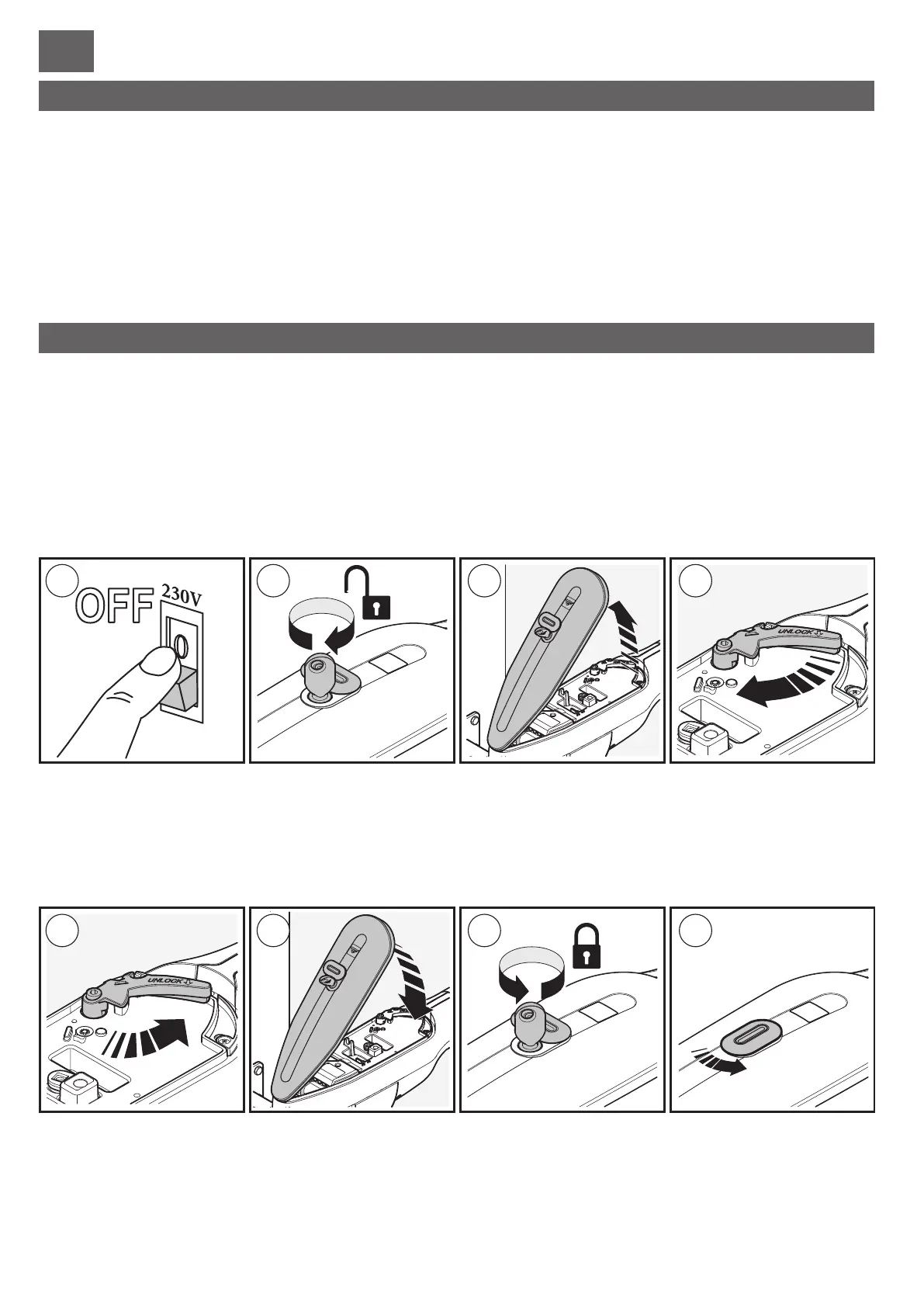
RELEASE AND LOCK PROCEDURE (irreversible models only)
These two operations are only required in the event of a fault or electrical power failure; the user or person responsible must be
instructed by the installer, who will provide them with a copy of these instructions, which must be kept in a safe place together
with the release key.
Before performing either of these procedures, make sure you disconnect the entire automation from the electrical
supply, even if it is currently unpowered due to an outage.
Any electric locks must be specified and released for manual operations.
RELEASE: 1) disconnect the electrical supply; 2) rotate the lock protection cover, insert the key and turn it clockwise; 3) raise
cover; 4) rotate the orange lever clockwise; the gate leaf can now be moved manually.
5) The leaf can remain unlocked and the cover can be refitted by simply removing the lever.
LOCK: 6) grasp the lever and rotate towards the rear of the actuator; at this point the leaf is locked and can only be moved
electrically.
7) After this operation always close the cover; 8) and turn the key to lock it in place; 9) take care to reclose the rubber cap
protecting the lock.
For REVERSIBLE models the gate can be operated manually after having released exclusively any electric locks
fitted.
ELECTRICAL CONNECTIONS
STANDARDS AND SAFETY
To gain access to the connections area first open the release lever cover then undo the screw shown in fig. M and remove the
casing. The connection cables enter the casing from under the motor unit (fig. N) through two cable glands.
Use extremely flexible cables that are suitable for the ambient conditions in the place of installation; a rigid cable
and/or one that is not approved for the specific application can impair the operation and safety of the automation.
The gear motor external cable must follow a loop path such that it does not create an obstruction and is not subject to
chafing during movement of the gate.
ENCODER
The actuators are all equipped with an encoder: a sensor that detects all speed changes and allows the Cardin control unit to
manage slowing down stages precisely and detect obstacles and stroke end stops.
Wherever possible, we recommend making this additional connection.
Note that all warranties concerning correct operation of the encoder are only applicable to Cardin products.
For the connections sequence refer to figs. L and O in the two versions (model BLADE 230V and BLADE 24V). The
recommended minimum wire cross section is 0.5 mm and the maximum length is 10 m.
With 230V BLADE models it is preferable to use a separate cable to connect the encoder to the control unit.
CONNECTION OF ACTUATOR BLADE3, BLADE3REV, BLADE5 and BLADE5REV.
To connect models equipped with a 230V motor refer to fig. L; the minimum wire cross section is 1.5 mm.
Connect the capacitor between the two motor phases.
CONNECTION OF MOTOR BLADE324, BLADE524 and BLADE524REV.
To connect models equipped with a 24V motor refer to fig. O; the recommended minimum wire cross section is 1.5 mm.
For connection distances greater than 10 m the minimum wire cross section is 2.5 mm.
Industry standard EN 12445 requires that all automations pass an impact test conducted using a specific test
instrument.
It is therefore necessary to carry out impact tests and adjust the control unit parameters until the reading is acceptable; if this
proves insufficient to bring the reading to within the limits shown in the chart specified by the standard, install a soft rubber
profile on the upper edge of the gate leaf to cushion the impact. If these measures are insufficient, install alternative devices
such as a sensitive safety edge along the gate leaf.
This product is made up of various components that could contain pollutants. Dispose of properly!
Make enquiries concerning the recycling or disposal of the product, complying with the local laws in
force.
DISPOSAL
- The CE conformity declaration for Cardin products is available in original language from the site www.cardin.it
under the section "Standards and Certification" via the link:
http://www.cardin.it/Attachment/dce156.pdf
1
1
2
2
3
3
4
4
 Loading...