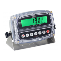
Model 190 Installation, Technical and Operation
8400-M022-O1 Rev J
3.6 Serial and I/O Cable Installation
3.6.1. Loosen the 4 Captive screws securing the rear housing to
the front housing assembly and then loosen a gland
connector for the serial cable. Refer to Figure No. 2 for an
illustration of the connector layout.
3.6.2. Slip the serial cable through the gland connector and into
the enclosure.
3.6.3. Remove 3" of the outer insulation jacket then remove 1/4"
of insulation from each of the wires (refer to Figure No. 3).
3.6.4. Remove the 9-connector terminal block connector from P3
on the 190 mainboard. Grasp the terminal block
connector and lift straight up away from the board.
3.6.5. Referring to the table below and the labels on the circuit
board for terminal connections, connect each wire to the
terminal block.
3.6.6. To terminate a wire, loosen the screws in the terminal
block and then insert the wire into the terminal opening.
Tighten the screw to secure the wire in place.
3.6.7. Repeat the procedure until all wires are in place.
3.6.8. After all terminations have been made, remove the excess
cable from the enclosure.
Figure No. 6

 Loading...