Updated:
17/03/2010
Ver. 1.1
Eng
Pag.6/12
TABLE OF OPERATING PARAMETERS
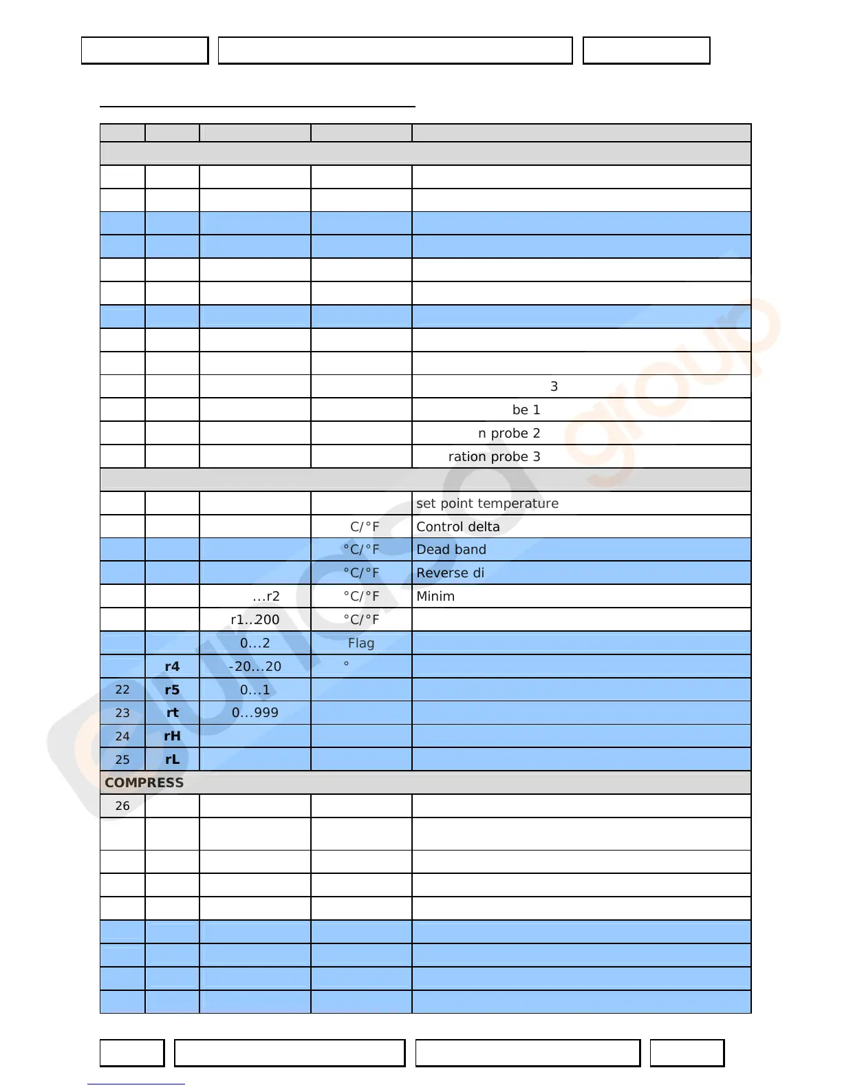
N° Code Range U.M. Description
TEMPERATURE PROBE MANAGEMENT PARAMETERS
1
/2 0...15 -- Measurement stability
2
/3 0...15 -- Probe display response
3
/4 0…100 -- Virtual probe
4
/5 0/1 Flag Selection °C or °F
5
/6 0/1 Flag Decimal point
6
/tl 1…6 -- Display on terminal
7
/tE 0...6 -- Display on external terminal
8
/P 0…2 -- Type of probe
9
/A2 0…3 -- Configuration probe 2
10
/A3 0…3 -- Configuration probe 3
11
/c1 -20…20 °C/°F (/10) Calibration probe 1
12
/c2 -20…20 °C/°F (/10) Calibration probe 2
13
/c3 -20…20 °C/°F (/10) Calibration probe 3
TEMPERATURE CONTROL PARAMETERS
14
St r1…r2 °C/°F set point temperature
15
rd 0.1…20 °C/°F Control delta
16
rn 0…60 °C/°F Dead band
17
rr 0.1…20 °C/°F Reverse differential for control with dead band
18
r1 -50...r2 °C/°F Minimum set point allowed
19
r2 r1…200 °C/°F Maximum set point allowed
20
r3 0...2 Flag Operating mode
21
r4 -20...20 °C/°F Automatic night-time set point variation
22
r5 0...1 °C/°F Enable temperature monitoring
23
rt 0...999 °C/°F Temperature monitoring interval
24
rH - °C/°F Maximum temperature read
25
rL - °C/°F Minimum temperature read
COMPRESSOR SAFETY TIME AND ACTIVATION PARAMETERS
26
c0 0...15 Minutes Compressor and fan delay on start-up
27
c1 0…15 Minutes
Minimum time between two sequent compressor
starts
28
c2 0...15 Minutes Minimum compressor OFF time
29
c3 0...15 Minutes Minimum compressor ON time
30
c4 0…100 Minutes Duty setting
31
cc 0…15 Hours Continuous cycle duration
32
c6 0…15 Hours Alarm bypass after continuous cycle
33
c7 0...900 Seconds Maximum pump down time
34
c8 0...60 Seconds Compressor start delay after open PD valve

 Loading...


