Do you have a question about the Carel IR33E9HR20 and is the answer not in the manual?
| Power Consumption | 4 VA max |
|---|---|
| Output Type | Relay |
| Protection Degree | IP20 |
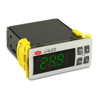
| Dimensions | 74 x 32 x 60 mm |
| Buzzer | Yes |
| Analogue Inputs | 2 |
| Output Rating | 8(3) A 250 Vac |
| Operating Temperature | -10 to 55 °C |
| Storage Temperature | -20°C to +70°C |
| Relative Humidity | non-condensing |
| Serial Port | TTL |