CAREL S.p.A.
Via dell’Industria, 11 - 35020 Brugine - Padova (Italy)
Tel. (+39) 0499716611 – Fax (+39) 0499716600
http://www.carel.com – e-mail: carel@carel.com
CAREL si riserva la possibilità di apportare modifiche o cambiamenti ai propri prodotti senza alcun preavviso.
CAREL reserves the right to modify the features of its products without prior notice.
cod. +050001040 rel. 1.4 - 09.10.2008
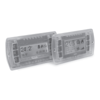
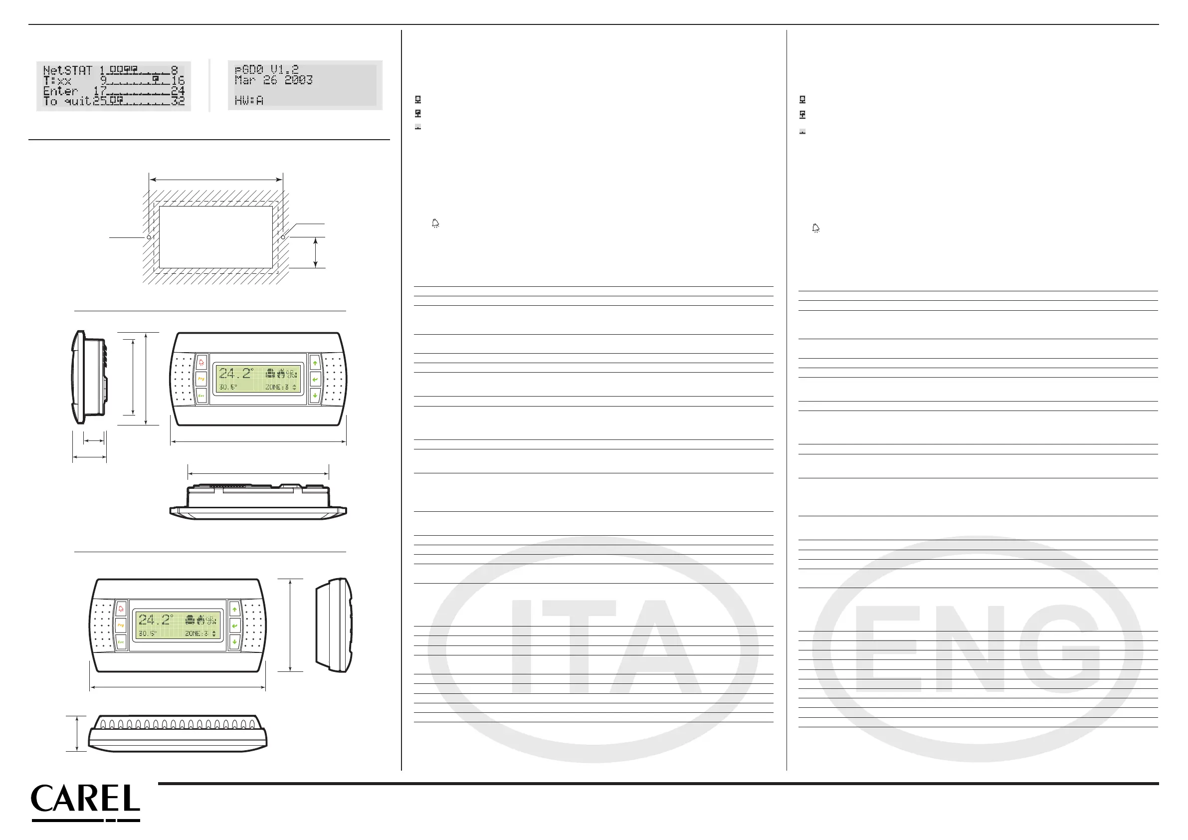
Visualizzazione stato rete e versione del firmware
Premendo contemporaneamente i tasti di configurazione (↓↑↵) per almeno 10 secondi (solo in modalità pLAN), si
visualizza la maschera di Fig. 6.
La schermata in Fig. 6 esemplifica lo stato della rete pLAN, visualizzando quanti e quali dispositivi sono collegati, e con quale
indirizzo.
Legenda:
: controllore pCO attivo in rete
:terminale attivo in rete
:nessun dispositivo collegato
Es. la Fig. 4 rappresenta:
controllori pCO attivi in rete con indirizzo: 1, 2, 25
terminali attivi in rete con indirizzo: 3, 4, 15, 26.
Tramite i tasti ↓↑ è possibile visualizzare la versione del firmware residente nel terminale (Fig. 7).
Per uscire dalla procedura NetSTAT premere il tasto ↵.
Regolazione contrasto LCD
I tasti + Prg + ↓↑ consentono la regolazione del contrasto.
Caratteristiche tecniche
Display
Tipo: grafico FSTN
Retroilluminazione: LED verdi (comandabile da “software applicativo”)
Risoluzione in grafica: 120x32 pixel
Modi testo: 4 righe x 20 colonne (font 5x7 e 11x15 pixel)
2 righe x 10 colonne (font 11x15 pixel)
oppure modi misti
Altezza carattere: 4,5 mm (font 5x7 pixel)
9 mm (font 11x15 pixel)
Dimensione area attiva: 71.95x20.75 mm
Dimensione area visiva: 76x25.2 mm
LED tastiera
2 programmabili da “software applicativo” di colore rosso e arancio (tasti Prg e Alarm)
4 di colore verde, asserviti al comando backlight dell’LCD (tasti ↓↑↵ e Esc)
Alimentazione
Tensione: alimentazione da pCO tramite connettore telefonico oppure da
sorgente esterna 18/30 Vdc protetta da fusibile esterno da 250 mAT
Potenza assorbita massima: 0,8 W
Distanze massime
Lunghezza massima rete pLAN: 500 m con cavo AWG22 a coppie schermate
Distanza pCO terminale: 50 m con cavo telefonico
500 m con cavo AWG22 a coppie schermate e TCONN6J000
Nota: per raggiungere la lunghezza massima utilizzare una
tipologia a bus con diramazioni che non superano i 5 m.
Materiali
Frontale trasparente: policarbonato trasparente
Retrocontenitori grigio antracite (parete/incasso): policarbonato +ABS
Tastiera: gomma siliconica
Vetrino trasparente/cornice: policarbonato trasparente
Autoestinguenza: V0 su frontale trasparente e retrocontenitori
HB su tastiera siliconica e particolari restanti
Generali
Grado di protezione: IP65 con montaggio a pannello
IP40 con montaggio a parete
UL type 1
Condizioni di funzionamento: -20T60 °C, 90% U.R. non condensante
Condizioni di immagazzinamento: -20T70 °C, 90% U.R. non condensante
Classe e struttura del software: A
Classificazione secondo il grado di
protezione contro le scosse elettriche: Da incorporare in apparecchiature di classe I o II
PTI dei materiali di isolamento: PCB: PTI 250; insulation material PTI 175
Periodo delle sollecitazioni elettriche: lungo
Categoria di resistenza al calore e al fuoco: D
Immunità contro le sovratensioni: Categoria II
Inquinamento ambientale: 2
Dimensioni / Dimensions
134
Ø 4
34.5
dima di foratura
drilling template
127x69 mm
Ø 4
156
125
67
18
30
82
82
31
156
Fig. 8
Fig. 9
Fig. 10
Displaying the status of the network and firmware version
Pressing the configuration buttons (↓↑↵) together for at least 10 seconds (in pLAN mode only), displays the screen shown in
Fig. 6.
The screen shown in Fig. 6 provides an example of the status of the pLAN, displaying which and how many devices are con-
nected, and the corresponding addresses.
Key:
: pCO controllers active in network
: terminals active in network
: no device connected
The example in Fig. 4 represents:
pCO controllers active in network, addresses: 1, 2, 25
terminals active in network, addresses: 3, 4, 15, 26.
The ↓↑ buttons can be used to display the version of the firmware resident in the terminal (Fig. 7).
To exit the NetSTAT procedure, press ↵.
Contrast adjustment
Use + Prg + ↓↑ buttons to adjust the contrast.
Technical specifications
Display
Type: FSTN graphic
Backlighting: green LEDs (controlled by “application software”)
Graphic resolution: 120x32 pixels
Text mode: 4 rows x 20 columns (font sizes 5x7 and 11x15 pixels)
2 rows x 10 columns (font size 11x15 pixels)
or mixed modes
Character height: 4.5 mm (font size 5x7 pixels)
9 mm (font size 11x15 pixels)
Size of active area: 71.95x20.75 mm
Size of display area: 76x25.2 mm
Keypad LEDs
2 programmable by “application software”, red and orange (Prg and Alarm buttons)
4 green LEDs, used as backlighting for LCD (↓↑↵ and Esc buttons)
Power supply
Voltage: power supply from pCO through telephone cable or external
source 18/30 Vdc protected with 2 250 mAT fuse
Maximum power input: 0.8 W
Maximum distances
Maximum pLAN length: 500 m with AWG22 twisted pair cable
pCO terminal distance: 50 m with telephone cable
500 m with AWG22 twisted pair cable and TCONN6J000
Note: to reach the maximum length, use a bus layout, with branches
not exceeding 5 m.
Materials
Transparent front panel: transparent polycarbonate
Charcoal grey container back piece (wall/built-in): polycarbonate +ABS
Keypad: silicon rubber
Transparent cover glass/frame: transparent polycarbonate
Self-extinguishing classification: V0 for transparent front panel and back piece
HB for silicon keypad and remaining parts
Others
Index of protection: IP65 for panel mounting
IP40 for wall mounting
UL type 1
Operating conditions: -20T60 °C, 90% r.H. non-condensing
Storage conditions: -20T70 *C, 90% r.H. non-condensing
Software class and structure: A
Classification according to
protection against electric shock: To be integrated into class 1 or 2 devices
PTI of insulating materials: PCB: PTI 250; insulation material PTI 175
Period of electric stress across insulating parts: long
Category of resistance to fire and heat: D
Immunity against voltage surges: Category II
Environmental pollution: 2
Fig. 6
Fig. 7
Assegnazione lista terminali privati e condivisi
Assigning the list of private and shared terminals

 Loading...