CAREL INDUSTRIES HQs
Via dell’Industria, 11 - 35020 Brugine - Padova (Italy)
Tel. (+39) 0499716611 – Fax (+39) 0499716600 – http://www.carel.com – e-mail: carel@carel.com
+0500086SV - rel. 2.7 -28.04.2020
Larmtabell /
Alarms table
(SOFTWARE RELEASE: 3.0)
Code Orsak till larmet
Cause of the alarm
Display icon
flashing
Display button
flashing
Alarm
relay
Buzzer Reset PD valve Compressor Defrost Evapor.
fans
Condens.
fans
Contin.
cycle
rE Fel på virtuell kontrollsond
Virtual control probe fault
ON ON automatic duty setting(c4) duty setting(c4) - - - OFF
E0 Fel sond B1
Probe B1 fault
ON ON automatic duty setting(c4) duty setting(c4) - - - OFF
E1 Fel sond B2
Probe B2 fault
ON ON automatic - - - - - OFF
E2 Fel sond B3
Probe B3 fault
ON ON automatic - - - - - -
E3 Fel sond B4
Probe B4 fault
ON ON automatic - - - - - -
E4 Fel sond B5
Probe B5 fault
ON ON automatic
LO Larm för låg temperatur
Low temperature alarm
- ON ON automatic - - - - - -
HI Larm för hög temperatur
High temperature alarm
-
ON ON automatic - - - - - -
IA Omedelbart larm från extern kontakt
Immediate alarm from external contact
- ON ON automatic duty setting (A6) duty setting(A6) OFF - - OFF
SA Allvarligt larm från extern kontakt
Serious alarm from external contact
- ON ON automatic OFF OFF OFF OFF OFF OFF
Pd Larm max stilleståndstid pump
Maximum pump down time alarm
- ON ON automatic - - - - - -
LP Lågtryckslarm
Low pressure alarm
- ON ON automatic OFF OFF OFF - - -
AtS Automatisk start stillastående pump
Autostart in pump down
- ON ON automatic/manual - - - - - -
CHt Larm hög temperatur kondensor
High condenser temperature alarm
- ON ON manual OFF OFF - - OFF -
dor Larm dörr öppen för länge
Door open for too long alarm
- ON ON automatic - - - - - -
Etc Fel realtidsklocka
Real time clock fault
ON ON automatic - - - - - -
EE Fel enhetsparameter EEPROM
Unit parameter EEPROM error
ON ON automatic - - - - - -
EF Fel driftsparameter EEPROM
Operating parameter EEPROM error
ON ON automatic - - - - - -
Ed1, Ed2 Avfrostning slutade vid timeout
Defrost ended by timeout
- ON ON automatic
HA Larm typ HA HACCP
Type HA HACCP alarm
-
ON ON manual - - - - - -
HF Larm typ HF HACCP
Type HF HACCP alarm
-
ON ON manual - - - - - -
LoG Temperaturhämtning misslyckades
Temperature downloload failed
- OFF ON automatic - - - - - -
uPL Parameteröverföring misslyckades
Parameters upload failed
- OFF ON automatic - - - - - -
dnL Parameterhämtning misslyckades
Parameters download failed
- OFF ON automatic - - - - - -
SOF Programuppdatering misslyckades
Software update failed
- OFF ON automatic - - - - - -
SHA/SHb
EVD 1/EVD 2- Lågt överhettningsskydd
EVD 1/EVD 2- Low superheat protection
-
ON ON automatic OFF OFF OFF - - -
LOA/LOb EVD 1/EVD 2- LOP-skydd
EVD 1/EVD 2- LOP protection
-
ON ON automatic OFF OFF OFF - - -
OA/Ob EVD 1/EVD 2- MOP-skydd
EVD 1/EVD 2- MOP protection
-
ON ON automatic OFF OFF OFF - - -
EEA/EEb EVD 1/EVD 2- Fel ventilmotor
EVD 1/EVD 2- Valve motor fault
-
ON ON automatic OFF OFF OFF - - -
LSA/LSb EVD 1/EVD 2- Låg sugtemperatur
EVD 1/EVD 2- Low suction temperature
-
ON ON automatic - - - - - -
Hit/Hib EVD 1/EVD 2- Skydd för hög kondenstemperatur aktiverat
EVD 1/EVD 2- High condensing temperature protec. activated
-
ON ON automatic - - - - - -
ES1/E1b EVD 1/EVD 2- Fel på sond S1 eller värde överstiger området
EVD 1/EVD 2- Probe S1 fault or value out of range
-
ON ON automatic OFF OFF OFF - - -
ES2/E2b EVD 1/EVD 2- Fel på sond S2 eller värde överstiger området
EVD 1/EVD 2- Probe S2 fault or value out of range
-
ON ON automatic OFF OFF OFF - - -
ES3/E3b EVD 1/EVD 2- Fel på sond S3 eller värde överstiger området
EVD 1/EVD 2- Probe S3 fault or value out of range
-
ON ON automatic - - - - - -
ES4/E4b EVD 1/EVD 2- Fel på sond S4 eller värde överstiger området
EVD 1/EVD 2- Probe S4 fault or value out of range
-
ON ON automatic - - - - - -
bAt/bAb
EVD 1/EVD 2- Batteri urladdat eller felaktigt eller elanslutning
avbruten
EVD 1/EVD 2- Battery discharged or faulty or electrical connec-
tion interrupted
-
ON ON automatic - - - - - -
EEE/EE2 EVD 1/EVD 2- Operating och/eller fel EEPROM-parameter
EVD 1/EVD 2- Operating and/or parameter EEPROM error
-
ON ON automatic OFF OFF OFF - - -
EIC/EIb EVD 1/EVD 2- Ventil inte fullständigt stängd
EVD 1/EVD 2- Valve not closed completely
-
ON ON automatic - - - - - -
EEC/E2C EVD 1/EVD 2- Ventil stängd i nödläge
EVD 1/EVD 2- Valve closed in emergency
-
ON ON automatic OFF OFF OFF - - -
EFu/EFb EVD 1/EVD 2- FW kompatibilitetsfel (FW EVO <5.6)
EVD 1/EVD 2- FW compatibility error (FW EVO <5.6)
-
ON ON automatic - - - - - -
ECn/ECb EVD 1/EVD 2- Konfigurationsfel
EVD 1/EVD 2- Configuration error
-
ON ON automatic - - - - - -
ELE/EL2 EVD 1/EVD 2- offline
EVD 1/EVD 2- offline
-
ON ON automatic OFF OFF OFF - - -
EGN/EG2 Gasfel inte kompatibelt med FW EVD1 / EVD2
Error: gas not compatible with FW EVD1/EVD2
ALM Hämtning av larmlogg misslyckades
Alarm log download failed
-
OFF ON automatic - - - - - -
EPE 3-fasig modul offline
3PH module off-line
-
ON ON automatic OFF OFF OFF OFF - -
EP0 Fel sond Sd1 (3-fasig modul)
Probe Sd1 fault (3PH module)
-
ON ON automatic - - End by time
if Sd1 only
- - -
EP1 Fel sond Sd2 (3-fasig modul)
Probe Sd2 fault (3PH module)
-
ON ON automatic - - - - - -
EP2 Fel sond Sc (3-fasig modul)
Probe Sc fault (3PH module)
-
ON ON automatic - - - - - -
EPn Konfigurationsfel 3-fasig modul
3PH module configuration fault
-
ON ON automatic OFF OFF OFF OFF - -
EPM Larm motorskydd (3-fasig modul)
Motor protector alarm (3PH module)
-
ON ON manual OFF OFF OFF OFF OFF -
EPU Larm hög-/lågtrycksbrytare eller Kriwan (3-fasig modul)
High/low pressure switch or Kriwan alarm (3PH module)
-
ON ON manual OFF OFF OFF OFF OFF -
AUH Larm hög fuktighet
High humidity alarm
- ON ON automatic - - - - - -
AUL Larm låg fuktighet
Low humidity alarm
- ON ON automatic - - - - - -
GH1 Allmänt högt larm (fas 1 ON/OFF - allmän funktion)
Generic High Alarm (stage 1 ON/OFF - generic function)
- ON ON automatic - - - - - -
GL1 Allmänt lågt larm (fas 1 ON/OFF - allmän funktion)
Generic Low Alarm (stage 1 ON/OFF - generic function)
- ON ON automatic - - - - - -
GH2 Allmänt högt larm (fas 2 - allmän funktion)
Generic High Alarm (stage 2 - generic function)
- ON ON automatic - - - - - -
GL2 Allmänt lågt larm (fas 2 - allmän funktion)
Generic Low Alarm (stage 2 - generic function)
- ON ON automatic - - - - - -
GH6 Allmänt högt larm (fas 3 ON/OFF - allmän funktion)
Generic high allarm (stage 3 ON/OFF - funz. generica)
- ON ON automatic - - - - - -
GL6 Allmänt lågt larm (fas 3 ON/OFF - allmän funktion)
Generic low alarm (stage 3 ON/OFF - funz. generica)
- ON ON automatic - - - - - -
GH3 Allmänt högt larm (modulering 1 - allmän funktion)
Generic High Alarm (modulation 1 - generic function)
- ON ON automatic - - - - - -
GL3 Allmänt lågt larm (modulering 1 - allmän funktion)
Generic Low Alarm (modulation 1 - generic function)
- ON ON automatic - - - - - -
GA1 Allmänt larm detekterat (larm 1 - allmän funktion)
Generic Alarm detected (alarm 1 - generic function)
- ON ON automatic - - - - - -
GA2 Allmänt larm detekterat (larm 2 - allmän funktion)
Generic Alarm detected (alarm 2 - generic function)
- ON ON automatic - - - - - -
IEC EVD ICE – Konfigurationsfel
EVD ICE – Configuration error
- ON ON automatic OFF OFF - - - OFF
IEM/IMb EVD 1/EVD 2 – Matchningsfel med UltraCella
EVD 1/EVD 2 – Mismatch error with UltraCella
-
ON ON manual
- - - - - -
Tekniska egenskaper
Matarspänning
Mod. 230V
Mod. 24V
Spänning 230 V~ (+10/-15%), 50/60 Hz; Effekt 18 VA, 100 mA~ max.
Spänning 24 V~ (+10/-15%), 50/60 Hz; Effekt 18 VA, 1A~ max.
Isolamento
garantito dall’
alimentaz. 230 V
Isolering i förhållande till mycket låg spänning: förstärkt, 6 mm i luften, 8
mm ytliga, 3750V. Isolering i förhållande till reläutgångar: huvudutgång,
3 mm i luften, 4 mm ytliga, 1250 V.
Analoga
ingångar
B1, B2, B3: NTC, PT1000 (±3%); B4: NTC, 0...10Vdc (±3%); B5: 0...5Vdc rratio-
metrisk (±3%), 4...20mA (±3%)
Analog utgång Y1: 0...10Vdc (10mA max, ±5%)
Observera Separera anslutningar för matarspänning och laddning från kablarna för
givare, digitala ingångar och övervakare under installationen.
Typ av givare NTC std. CAREL: 10 kΩ a 25°C,
intervall från
-50°C a 90°C;
mätfel
: 1°C
inter-
vall från
-50°C a +50°C; 3°C
intervall från
+50°C a +90°C
NTC HT: 50 kΩ a 25°C,
intervall från
0°C a 150°C;
mätfel
: 1,5°C
intervall från
0°C a +115°C; 4°C
intervall från
+115°C a +150°C
PT1000 std. CAREL: 1000Ω a 0°C,
intervall från
–50°C a +90°C;
mätfel
3°C
intervall från
–50°C a 0°C; 5°C
intervall från
0°C a +90°C
Matarspänning
aktiva givare
+Vdc: 12V+-30%, 25mAmax; 5VREF: 5V+-2%
Reläutgångar Tillämpbara intervall beroende på typ av relä
Tipo relè EN60730 -1 (250 V ~) UL 873 (250 V ~)
8A (AUX1,AUX2) 8(4)A su N.O.; 6 (4)A su N.C.;
2(2)A su N.C. e N.O. (100000cicli)
8A resistivi 2FLA 12LRA,
C300 (30000 cicli)
16A (LIGHT, FAN) 10A res., 5 (3)A (100000 cicli) 10A resistivi, 5FLA 18LRA
(30000 cicli)
30A (COMP, DEF) 12 (10)A (100000 cicli) 12A resistivi, 2HP, 12FLA
72LRA (30000 cicli)
Observera: Den totala strömbelastningen COMP, DEF, FAN som tänds
samtidigt får inte överstiga 20A.
Isolering Isolering i förhållande till mycket låg spänning: förstärkt, 6 mm i luften, 8
mm ytliga; 3750 V.
Isolering i förhållande till oberoende reläutgångar: huvudutgång, 3 mm i
luften, 4 mm ytliga; 1250 V.
Anslutningar Sektion kontaktdon för analoga in- och utgångar, digitala ingångar, seriel-
la: från 0,5 till 2,5mm
2
(från 20 till 13 AWG);
Sektion kontaktdon för matarspänning och laster: från 1,5 till 2,5 mm
2
(från 15 till 13 AWG)
Seriella anslutningar: använd skärmade kablar
Kablarnas maxlängd: 10m
Behållare Plast: dimension 200 x 100 X 190 mm
Montering På väggen (med plastbehållare): med fästskruvar frontalkort
Display LED-display: 3 och 4 digit, visning från -99 till 999; driftstillstånd anges
med lysdioder och grafiska symboler som avbildats på polykarbonat
fastsatt på plastbehållaren
Tangentbord 10 tang. på tangentbordet i polykarbonatmembran fastsatt på plastbehållaren
Klocka med
buffertbatteri
Tillgänglig
Buzzer Tillgänglig på alla modeller
Klocka Precision: ±100 ppm; Batteri: typ “knappceller” med litium kod. CR2430
spänning: 3Vdc (dimension 24x3 mm)
Seriella
tillgängliga
3 typer: pLAN, BMS, Fieldbus
pLAN: Driver HW RS485, telefonjack (befintlig beroende på modell) och
skruvplintar
BMS: Driver HW RS485, skruvplintar
Fieldbus: Driver HW RS485, skruvplintar
USB Typ: Host (kontaktdon typ A); matarspänning 5Vdc, max absorption:
100mA (low power devices)
Driftsförhållan-
den
Tomt kort: -10T65°C; <90% U.R. icke-kondenserande
Med plastbehållare: -10T50°C, <90% U.R. icke-kondenserande
Identifier. av reläer, typ och maximal resistiv ström vid drifttemperatur:
Relä Belastningsvärde
Typ av
relä
Max tillämpbar res. ström
R1 (AUX2) 8A 8A
R2 (AUX1) 8A 8A
R3 (LIGHT) 16A 10A
R4 (FAN) 16A 10A
R5 (DEF) 30A 12A
R6 (COMP) 30A 12A
Observera: den totala strömbelastningen (COMP), (DEF), (FAN) som tänds
samtidigt får inte överstiga 20 A.
Lagringsförhållanden -20T70°C, < 90% U.R. icke-kondenserande
Främre skyddsgrad Med plastbehållare: IP65
Miljöförorening 2, normal situation
PTI på isoleringsmaterialen Kretskort 250, plast och isolerande material 175
Kategori av brandsäkerhet Kategori D
Skyddsklass mot överspänning Kategori II
Typ av åtgärd och urkoppling Reläkontakter 1B (Mikrourkoppling)
Konstruktion på styranordningen Inbyggd styranordning, elektronisk
Klassificerad i enlighet med skydd mot
elolyckor
Klass II utan jordanslutning
Klass I med jordanslutning
Anordning som är avsedd att hållas i hand
eller införlivas i en anordning som är avsedd
att hållas i hand
Nej
Klass och struktur på mjukvaran Klass A
Främre rengöring av kontrollen använd endast neutrala rengöringsmedel
och vatten
Technical specications
Power supply
230 V model
24 V model
Voltage 230 V~ (+10/-15%), 50/60 Hz; Power 18 VA, 100 mA~ max.
Voltage 24 V~ (+10/-15%), 50/60 Hz; Power 18 VA, 1A~ max.
Insulation guaran-
teed from 230V
power supply
Insulation from extra low voltage parts: reinforced, 6 mm clearance,
8 mm creepage, 3750V. Insulation from relay outputs: basic, 3 mm
clearance, 4 mm creepage, 1250 V.
Analogue inputs B1, B2, B3: NTC, PT1000 (±3%); B4: NTC, 0 to 10 Vdc (±3%); B5: 0 to 5
Vdc ratiometric (±3%), 4 to 20 mA (±3%)
Analogue output Y1: 0 to 10 Vdc (10 mA max, ±5%)
Note In the installation, separate the power and load connections from the
probe, digital input and supervisor cables.
Probe type Std. CAREL NTC: 10 kΩ at 25°C, range from -50°C to 90°C; measure-
ment error: 1°C in the range from -50°C to +50°C; 3°C in the range
from +50°C to +90°C
NTC HT: 50 kΩ at 25°C, range from 0°C to 150°C; measurement error:
1.5°C in the range from 0°C to +115°C; 4°C in the range from +115°C
to +150°C
Std. CAREL PT1000:1000Ω to 0°C, range from –50°C to +90°C; mea-
surement error 3°C in the range from –50°C to 0°C; 5°C in the range
from 0°C to +90°C
Power to active
probes
+Vdc: 12 V+-30%, 25 mA max; 5 V REF: 5V+-2%
Relay outputs Applicable rating depending on the type of relay
Relay type EN60730 -1 (250 V ~) UL 873 (250 V ~)
8A (AUX1,AUX2) 8 (4)A on N.O.; 6 (4)A
on N.C.; 2 (2)A on N.C. &
N.O. (100000 cycles)
8A resistive 2FLA 12LRA, C300
(30000 cycles)
16A (LIGHT,
FAN)
10A resistive, 5 (3)A
(100000 cycles)
10A resistive, 5FLA 18LRA
(30000 cycles)
30A (COMP,
DEF)
12 (10)A (100000 cycles) 12A resistive, 2HP, 12FLA
72LRA (30000 cycles)
Note: The sum of the current to the loads (COMP, DEF, FAN)
when on at the same time must never exceed 20 A.
Insulation Insulation from extra low voltage parts: reinforced; 6 mm clearance, 8
mm creepage; 3750 V
Insulation between independent relay outputs: main; 3 mm clearan-
ce, 4 mm creepage; 1250 V
Connections Wire cross-section for analogue inputs and outputs, digital inputs,
serial: from 0.5 to 2.5mm
2
(from 20 to 13 AWG);
Wire cross-section for power supply and loads: from 1.5 to 2.5
mm
2
(from 15 to 13 AWG)
Serial connections: use shielded cables
Maximum cable length: 10m
Case Plastic: dimensions 200 x 100 x 190 mm
Assembly Wall mounting (with plastic case): by fastening screws through front
board
Display LED display: 3 and 4 digits, display from -99 to 999; operating status
indicated by LEDs and graphic icons visible on polycarbonate applied
to the plastic case
Keypad 10 buttons on membrane polycarbonate keypad applied to the
plastic case
Clock with
battery backup
Available
Buzzer Available on all models
Clock Precision: ±100 ppm; battery: lithium button battery type CR2430
voltage: 3 Vdc (dimensions 24x3 mm)
Serial port available 3 types: pLAN, BMS, Fieldbus
pLAN: RS485 HW driver, telephone jack (available according to the
model) and screw terminals
BMS: RS485 HW driver, screw terminals
Fieldbus: RS485 HW driver, screw terminals
USB Type: Host (type A connector); power supply 5 Vdc, max current: 100
mA (low power devices)
Operating
conditions
Open board: -10T65°C; <90% RH non-condensing
With plastic case: -10T50°C, <90% RH non-condensing
Identification of relays, type and maximum resistive current at ope-
rating temp.:
Relay Associated load Relay type Max applicable res. current
R1 (AUX2) 8A 8A
R2 (AUX1) 8A 8A
R3 (LIGHT) 16A 10A
R4 (FAN) 16A 10A
R5 (DEF) 30A 12A
R6 (COMP) 30A 12A
Note: the sum of the current to the loads (COMP), (DEF), (FAN) when
on at the same time must not exceed 20 A
Storage conditions -20T70°C, < 90% RH non-condensing
Front panel ingress protection With plastic case: IP65
Environmental pollution 2, normal situation
PTI of the insulating materials Printed circuits 250, plastic and insulating
materials 175
Category of resistance to fire Category D
Class of protection against voltage surge Category II
Type of action and disconnection Relay contacts 1 B (microswitching)
Construction of the control device Integrated electronic control device
Classification according to protection
against electric shock
Class II without earth terminal
Class I with earth terminal
Device designed to be hand-held or
integrated into equipment designed to
be hand-held
No
Software class and structure Class A
Cleaning of controller front panel Only use neutral detergents and water
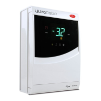
I den ociella You Tube CAREL-kanalen nns tutorials
tillgängliga för installation och konguration av Ultracella /
In
the ocial You Tube CAREL channel, tutorials are available for
installation and conguration Ultracella
 Loading...
