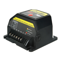
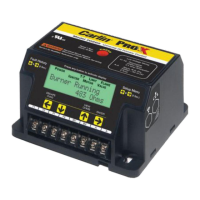
Model 40200/42230
CAD Cell Oil Primary Control
Data Sheet
• Oil Pump Bleed Assist
Up to 1 min.
• Recycle on Flame Failure
• Serviceman Reset Protection
Latch-up after 3 consecutive lockouts
• Diagnostic LEDs
Status, lockout, ame
• 15-second, 30-second TFI
• Increased Flame Accuracy
• Thermostat/Aquastat Compatible
• Improved SMC Technology
Zero bleed voltage during standby
• Works Well with Generators
Insensitive to frequency changes
• Flame Stabilize
Tech Support (800) 989-2275 www.carlincombustion.com
Power input (from limit circuit) 120 VAC, 60 HZ, 10 VA
Motor load
10 FLA / 60 LRA
Ignitor load
120 VAC, 60 HZ, 500 VA
Operating temperature limits
+32°F to +140°F
Storage temperature limits
-40°F to +185°F
Thermostat anticipator current
0.1 A, AC
CAD cell resistance (with flame) R < 1500 OHMS
Agencies
UL recognized (US & Canada)
Installing and Wiring
40200 and 42230 controls must be installed and serviced only by a qualified service technician.
1. Always disconnect power source before wiring to avoid electrical shock or damage to the control. All wiring must
comply with applicable codes and ordinances.
2. Thermostat terminals (T-T) provide a current source. Never apply external power to these terminals under any
circumstances.
Mounting
• The control may be mounted on a 4" x 4" junction box in any convenient location on the burner, furnace or wall.
The location must not exceed the ambient temperature limit, 140°F.
Wiring
• Wiring must comply with local and national electrical codes, and with the wiring diagram.
• Individual or bundled neutrals may be attached to any L2 terminal.
Field checks
1. Safety timing (TFI) test – Remove one cad cell wire (F-F). Start burner. The control should lockout within the TFI
time limit. Replace cad cell wire.
2. Flame failure test – Start burner. After ame is established (after TFI period), close the oil supply hand valve. This
will cause a flame failure sequence as described in the Startup & Operation section of this Data sheet. The control
should recycle (restart after 65 seconds).
3. If control does not operate as described, check the wiring.
SEE WIRING DIAGRAM ON NEXT PAGE