Do you have a question about the Carrier TRANSICOLD PrimeLINE 69NT40-571 and is the answer not in the manual?
| Brand | Carrier TRANSICOLD |
|---|---|
| Model | PrimeLINE 69NT40-571 |
| Category | Air Conditioner |
| Language | English |
General safety notices supplement specific warnings and cautions for operation and maintenance.
Precautions to follow during operation, including wearing safety glasses and ensuring power is off.
Precautions for maintenance, including avoiding unannounced starting and securing power.
Explanation of hazard levels (DANGER, WARNING, CAUTION) and their consequences.
Details on R-134a and R-513A refrigerant compatibility and conversion.
Description of key unit features like control box, compressor, and controller.
Descriptions of optional equipment available for the base unit.
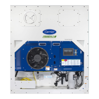
Overview of accessible components from the front of the refrigeration unit.
Description of the compressor and its related components.
Details on the air-cooled condenser, its components, and operation.
Description of the evaporator section and its components.
Description of the control box contents and components.
Table containing essential refrigeration system specifications.
Table detailing electrical specifications for unit components.
Overview of safety devices and their settings that protect the unit.
Explanation of the refrigeration circuit operation in different modes.
Description of the Micro-Link 5 microprocessor system.
Details on the controller's configuration and operational software.
General operation sequences for cooling, heating, and defrost.
Explanation of the alarm system and how alarms are generated.
Procedures for performing pre-trip inspections and tests.
Methods for connecting to the controller via USB or wireless.
Description of the DataCORDER system and its functions.
Pre-operation checks to ensure the unit is in proper condition.
Instructions for connecting the unit to power sources.
Procedures for safely starting and stopping the refrigeration unit.
Checks to perform after starting the unit to ensure proper operation.
Guide to initiating and performing pre-trip inspections.
Procedure for checking temperature probe accuracy and agreement.
Instructions for enabling various operating modes like QUEST and FuelWise.
Troubleshooting steps for units that fail to start or stop intermittently.
Troubleshooting for units that run excessively during cooling.
Steps to diagnose and resolve insufficient cooling issues.
Troubleshooting for units failing to heat or providing insufficient heat.
Steps to address units that fail to stop heating.
Troubleshooting for units that do not defrost correctly.
Diagnosing issues related to abnormal system pressures.
Troubleshooting guide for unexpected noises or vibrations.
Troubleshooting steps for microprocessor control issues.
Diagnosing and resolving issues with evaporator air flow.
Troubleshooting steps for EEV malfunctions.
Troubleshooting steps for autotransformer issues.
Troubleshooting for water-cooled condenser and pressure switch problems.
Troubleshooting steps for compressor operating in reverse.
Diagnosing and resolving abnormal temperature readings.
Troubleshooting abnormal current readings.
Description and use of the manifold gauge set for system service.
Information on accessing service valves and making connections.
Procedures for pumping down the unit before service.
Methods for checking the system for refrigerant leaks.
Procedures for evacuating and dehydrating the refrigeration system.
Procedures for checking and adding refrigerant charge.
Steps for converting the unit to use R-513A refrigerant.
Service information for the compressor, including removal and replacement.
Procedures for checking and replacing the high pressure switch.
Service information for the condenser coil, including cleaning and replacement.
Step-by-step guide for installing the condenser coil assembly.
Service information for the condenser fan and motor.
Procedures for cleaning the water-cooled condenser.
Procedures for checking and replacing the filter drier.
Service information for the evaporator coil, including replacement.
Information on evaporator heaters and testing procedures.
Procedure for testing heater insulation resistance.
Service information for the evaporator fan and motor assembly.
Steps for removing and replacing the evaporator fan assembly.
Procedures for cleaning the evaporator section.
Service information for the EEV, including removal and installation.
Service information for the ESV, including removal and installation.
Service information for the EXV, including removal and installation.
Troubleshooting steps for the Digital Unloader Valve (DUV).
Service information for the DUV, including removal.
Description of valve override controls for troubleshooting.
Procedures for controller service, handling, and replacement.
Procedures for programming the controller via USB.
Service procedures for various temperature sensors.
Service information for the humidity sensor, including checking operation.
Information on the vent position sensor and its calibration.
Information on the optional cargo sensor and its operational values.
Reference to procedures for EverFRESH controlled atmosphere system.
List of symbols and descriptions for the standard unit wiring diagram.
Electrical schematic diagram for the standard unit.
Wiring diagram for the standard unit, sheet 1.
Wiring diagram for the standard unit, sheet 2.
List of symbols and descriptions for units with the EverFRESH option.
Electrical schematic diagram for units with the EverFRESH option.
Wiring diagram for units with EverFRESH option, sheet 1.
Wiring diagram for units with EverFRESH option, sheet 2.

