ELECTRICAL SHOCK HAZARD
Failure to follow this warning could lead to electrical shock
resulting in personal injury or death.
To avoid personal injury, make sure electrical supply power
is off before servicing.
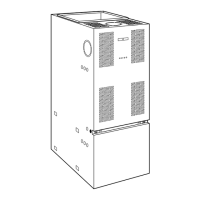
Step 1—General
In order to keep this furnace in good operating condition and to
maintain its warranty, the furnace MUST be serviced on an annual
basis. This servicing includes a nozzle change, a burner inspection,
a visual check of tube passages through flue outlet and cleanout
ports, and a visual inspection of combustion chamber when burner
is removed.
Depending on above inspection, service could also include a
cleaning and vacuuming of heat exchanger tubes and possibly the
heat exchanger drum section.
Removal of any heat exchanger components which are sealed by
gaskets requires replacement of gasket.
Table 13—58VMR105 Size Airflow Data (CFM)
OIL HEATING MODE
24 VAC INPUT (R) ON W ONLY
SW1-HEAT
Dip Switch Position
HEAT INPUT
(USGPH)
CFM with SW3-ADJ
Dip Switch A Position
CFM with SW3-ADJ
Dip Switch B Position
CFM with SW3-ADJ
Dip Switch C Position
A (1=OFF, 2=OFF) 0.75 1260 1425 1070
B (1=ON, 2=OFF) 0.65 1050 1190 895
C (1=OFF, 2=ON) 0.5 850 960 725
D (1=ON, 2=ON) Same Value then A Dip Switch Position
CONTINUOUS FAN
24 VAC INPUT (R) ON G ONLY
SW2-COOL
Dip Switch Position
A/C Size
(TON)
CFM with ADJ
Dip Switch A Position
CFM with ADJ
Dip Switch B Position
CFM with ADJ
Dip Switch C Position
A (1=OFF, 2=OFF) 3.0 785 905 670
B (1=ON, 2=OFF) 2.5 655 755 560
C (1=OFF, 2=ON) 2.0 525 605 445
D (1=ON, 2=ON) 1.5 395 455 335
COOLING OR HEAT PUMP HEATING MODE - SINGLE SPEED OR 2-SPEED HIGH
24 VAC INPUT (R) TO G, Y/Y2 AND O (FOR COOLING)
SW2-COOL
Dip Switch Position
A/C Size
(TON)
CFM with SW3-ADJ
Dip Switch A Position
CFM with SW3-ADJ
Dip Switch B Position
CFM with SW3-ADJ
Dip Switch C Position
A (1=OFF, 2=OFF) 3.0 1050 1155 945
B (1=ON, 2=OFF) 2.5 875 965 790
C (1=OFF, 2=ON) 2.0 700 770 630
D (1=ON, 2=ON) 1.5 525 580 475
NOTE: In cooling-Dehumidification mode, with no 24 VAC input to DH, the CFM-STD is reduced by 15%
COOLING MODE OR HEAT PUMP HEATING MODE - 2-SPEED LOW
24 VAC INPUT (R) TO G, Y1 AND O (FOR COOLING)
SW2-COOL
Dip Switch Position
A/C Size
(TON)
CFM-STD with SW3-ADJ
Dip Switch A Position
CFM-HIGH with SW3-ADJ
Dip Switch B Position
CFM-LOW with SW3-ADJ
Dip Switch C Position
A (1=OFF, 2=OFF) 3.0 580 635 520
B (1=ON, 2=OFF) 2.5 480 530 435
C (1=OFF, 2=ON) 2.0 385 425 345
D (1=ON, 2=ON) 1.5 290 320 260
NOTE: In Cooling-Dehumidification mode, with no 24 VAC input to DH, the CFM-STD is reduced by 15%
DELAY PROFILE FOR OIL HEATING MODE
SW4-DELAY
Dip Switch Position
HEAT INPUT
(USGPH)
On-Delay Time
Short Run On-Delay
CFM Level - Time
Off-Delay
CFM Level - Time
A (1=OFF, 2=OFF) 0.75 45 sec 19% - 30 sec 38% - 3 min.
B (1=ON, 2=OFF) 0.65 45 sec 19% - 30 sec 38% - 3 min.
C (1=OFF, 2=ON) 0.5 60 sec 13% - 30 sec 38% - 3 min.
D (1=ON, 2=ON) All 30 sec 100% - 0 sec 100% - 2 min.
Short Run is the time before the blower start at normal speed, with very low CFM, to minimize cool draft in the air distribution system.
Off Delay is the time required to cool down the heat exchanger, with low CFM, to minimize cool draft in the air distribution system.
DELAY PROFILE FOR COOLING OR HEAT PUMP HEATING MODE
No Adjustment
Required
A/C Size
On-Delay
Time
Short Run On-Delay
CFM Level - Time
Off-Delay
CFM Level - Time
- All 30 sec 75% - 2.5 min. 50% - 3 min.
Short Run is the time before the blower start at normal speed, with lower CFM, to minimize cool draft in the air distribution system.
Off Delay is the time required to cool down the coil (heating mode), with low CFM, to minimize cool draft in the air distribution system.
13
 Loading...

