NOTES:
1. For flanged waterbox nozzles, refer to the certified drawings for length addition measurements.
2. Service access should be provided based on American Society of Heating, Refrigeration, and Air Conditioning Engineers
(ASHRAE) 15, latest edition, National Fire Protection Association (NFPA) 70, and local safety codes.
3. A minimum 6 in. (152 mm) overhead clearance for service rigging is recommended.
4. Certified drawings are available upon request.
5. [ ] indicates millimeters.
HEAT EXCHANGER
(Cooler and
Condenser Size)
A (LENGTH)
OVERALL
B (WIDTH)
OVERALL
C (HEIGHT)
NOZZLE PIPE SIZE (in.)
(Nominal Pipe Size)
2 Pass* 1 or 3 Pass†
ft-in. mm ft-in. mm ft-in. mm ft-in. mm 1-Pass 2-Pass 3-Pass
40-43 13-7
3
⁄
4
4159 14-3
1
⁄
4
4350 5-10
7
⁄
8
1800 7-6
11
⁄
16
2303 10 8 6
HEAT EXCHANGER
(Cooler and
Condenser Size)
A (Length With
Marine Waterbox — Not Shown)
2 Pass* 1 or 3 Pass†
ft-in. mm ft.-in. mm
40-43 14-9
5
⁄
8
4512 16-5
1
⁄
2
5017
*Assumes both cooler and condenser nozzles on same end of chiller.
†1 or 3 pass length applies if either (or both) cooler or condenser isa1or3pass
design.
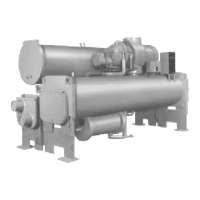
Fig. 7 — 23XL Dimensions (Frame 4 Machines)
9

 Loading...


