3
Table 1 – Accessory Usage
ACCESSORY
REQUIRED FOR
L O W --- A M B I E N T C O O L I N G
APPLICATIONS
(Below 55°F/12.8_C)
REQUIRED FOR LONG LINE AP-
PLICATIONS*
(Over 80 ft/24.38 m)
REQUIRED FOR SEA C OAST
APPLICATIONS (Within 2
miles/3.22 km)
Crankcase Heater Standard Standard Standard
Evaporator Freeze Protection
Standard with Infinityt Control
(Low Ambien t not allowed with
non--- communicating thermostat)
No No
Liquid--- Line Solenoid Valve No No No
Low---Ambient C ontrol
Standard with Infinity Control
(Low ambient not allowed with
non--- communicating thermostat)
No No
Puron Refrigerant Balance Port Hard ---
ShutOff TXV
Ye s {
Ye s {
Ye s {
Support Feet Recommended No Recommended
Winter Start Control
Standard with Infinity Control
(Low Ambient not allowed with
non--- communicating thermostat)
No No
* For tubing set l engths between 80 and 200 ft. (24.38 and 60.96 m) h o rizontal or 35 ft. (10.7 m) ver tical differential (total equivalent length), refer to the Long
Line Guideline—Air Conditioners and Heat Pumps using Puron® Refrigerant.
{ Required on all indoor units. Standard on all new Puron refrigerant fan coils and furnace coils.
Outdoor Uni t Connected to Factory Approved Indoor
Unit
Outdoor unit contains correct system refrigerant charge for
operation with factory approved AHRI rated indoor unit when
connected by 15 ft. (4.57 m) of field--supplied or factory--accessory
tubing, and factory supplied filter drier. Check refrigerant charge
for maximum efficiency.
NOTE: If the indoor furnace coil width is more than the furnace
casing width, refer to the indoor coil Installation Instructions for
transition requirements.
Refrigerant Tubing Connection Outdoor
Connect vapor and liquid tubes to fittings on vapor and liquid
service valves (see Table 1.) Use refrigerant grade tubing
Sweat Connection
CAUTION
!
UNIT DAMAGE HAZARD
Failure to follow this caution may result in equipment
damage or improper operation.
Service valves must be wrapped in a heat--sinking material
such as a wet cloth while brazing.
Use refrigeration grade tubing. Service valves are closed from
factory and ready for brazing. After wrapping service valve with a
wet cloth, braze sweat connections using industry accepted
methods and materials. Consult local code requirements.
Refrigerant tubing and indoor coil are now ready for leak testing.
This check should include all field and factory joints.
Table 1 – Refrigerant Connections and Recommended Liquid
and Vapor Tube Diameters (In.)
UNIT SIZE
(SERIES)
LIQUID RATED VAPOR*
Connection
&Max.Tube
Diameter
Connection
Diameter
Tube
Diameter
24 3/8 3/4 3/4
36 3/8 7/8 7/8
48 3/8 7/8 1-1/8
60 3/8 7/8 1-1/8
* Units ar e rated with 25 ft. (7.6 m) of lin eset. See Product Data sheet for
performance data when using different size and length linesets.
Notes:
1. Do not apply capillary tube or fixed orifice indoor coils to these units.
2. For Tubing Set lengths between 80 and 200 ft. (24.38 and 60.96 m)
horizontal or 35 ft. (10.7 m) vertical differential 250 ft. ( 76.2 m) Total
Equivalent Length), refer to the Residential Piping and Longline Guide
line--- Air Conditioners and Heat Pumps using Puron refrigerant.
3. For alternate liquid line options on 18---42 size units, see Product Data or
Residential Piping and Application Guideline
Install Liquid--Line Filter Drier Indoor
CAUTION
!
UNIT DAMAGE HAZARD
Failure to follow this caution may result in equipment
damage or improper operation.
1. Installation of filter drier in liquid line is required.
2. Filter drier must be wrapped in a heat--sinking material
such as a wet cloth while brazing.
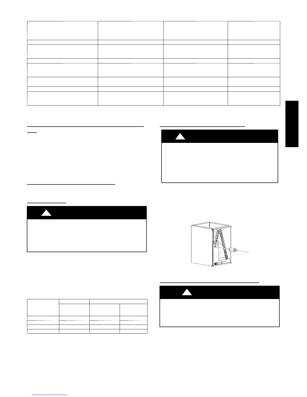
Refer to Fig. 3 and install filter drier as follows:
1. Braze 5 -- in. liquid tube to the indoor coil.
2. Wrap filter drier with damp cloth.
3. Braze filter drier to above 5-- in. (127 mm) liquid tube.
Flow arrow must point towards indoor coil.
4. Connect and braze liquid refrigerant tube to the filter drier.
A05178
Fig. 3 -- Liquid Line Filter Drier
Evacuate Refrigerant Tubing and Indoor Coil
CAUTION
!
UNIT DAMAGE HAZARD
Failure to follow this caution may result in equipment
damage or improper operation.
Never use the system compressor as a vacuum pump.
Refrigerant tubes and indoor coil should be evacuated using the
recommended deep vacuum method of 500 microns. The alternate
triple evacuation method may be used (see triple evacuation
procedure in service manual). Always break a vacuum with dry
nitrogen.
24APA7

 Loading...